Design
D - 29
In the diagram above
G : Position of center of gravity of equipment
W : Self weight of equipment (N)
R
b
: Pull out strength of 1 foundation bolt (N)
n : Total no. of foundation bolts
n
t
: The no. of foundation bolts on one side that would be
subject to tension if the equipment was overturning
(no. of bolts provided on one side in the direction
being considered)
h
G
: Height from the installation surface to the unit’s center
of gravity(mm)
l : Bolt span seen from the direction under consideration
(mm)(l
1
:Short direction,l
2
:Long direction)
l
G
: Distance from the center of the bolt to the center of
gravity of the equipment seen from the direction under
consideration (but l
G
l/2(mm))
F
H
: Design horizontal force (N)
(F
H
= K
H
•W)
F
V
: Design vertical force (N)
A : Nominal cross-sectional area of one foundation bolt
(mm
2
)
τ : Shear stress acting on the bolt (N/mm
2
)
f
ts
: Allowable tensile stress in a bolt in which shear stresses
are simultaneously acting (N/mm
2
)
However, f
ts
f
t
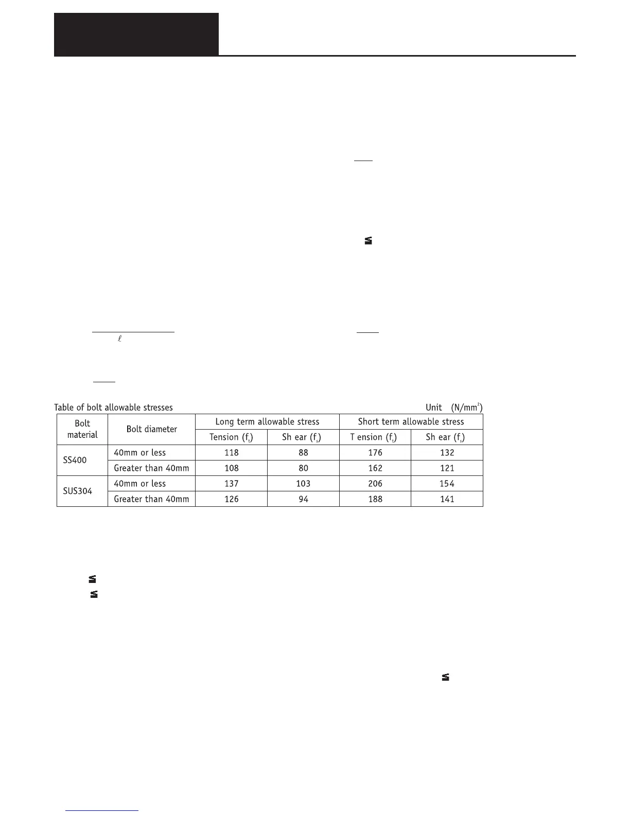
• Foundation bolt pull out force
• Foundation bolt shear stress
• Foundation bolt tensile stress
•Allowable tensile stress in a bolt in which shear stresses are
simultaneously acting
Notes
1) The values in the above table have been derived from “Steel structures design criteria” published by the
Architects Institute of Japan.
2) If it is necessary to investigate the bolt tensile stress then the value f
t
in the table should be used.
3) A check on the strength of a bolt subject to simultaneous tension and shear is carried out as follows.
a) τ
f
s
b) σ the smallest of f
t
and f
ts
, however, f
ts
=1.4f
t
-1.6τ
here
τ : Shear stress on the bolt
σ : Tensile stress in the bolt (σ = R
b
/A)
f
s
: Allowable shear stress in the bolt (shear stress only: value from the above table)
f
t
: Allowable tensile stress in bolt (tensile stress only: value from above table)
f
ts
: Allowable tensile stress in bolt subject to simultaneous tension and shear however, f
ts
f
t
4) The allowable tensile stresses in the above table are evaluated using the cross-sectional area of the minor
diameter of the screw thread. However, for calculations for selection purposes, it is sufficient to use the cross-
sectional area based upon the nominal diameter.
5) If the threaded portion is subjected to shear, then when using the cross-sectional area based upon the nominal
diameter, the value of ‚†
s
in the above table should be multiplied by 0.75.
F
v
= F
H
2
1
R
b
=
F
H
h
G
-(W-F
V
) l
G
..
.
nt
τ =
F
H
.
n A
δ =
R
b
A
F
ts
= 1.4f
t
- 1.6τ
7. Center of gravity position and earthquake resistant design