Design
D - 38
(4) Example anchor bolt calculation
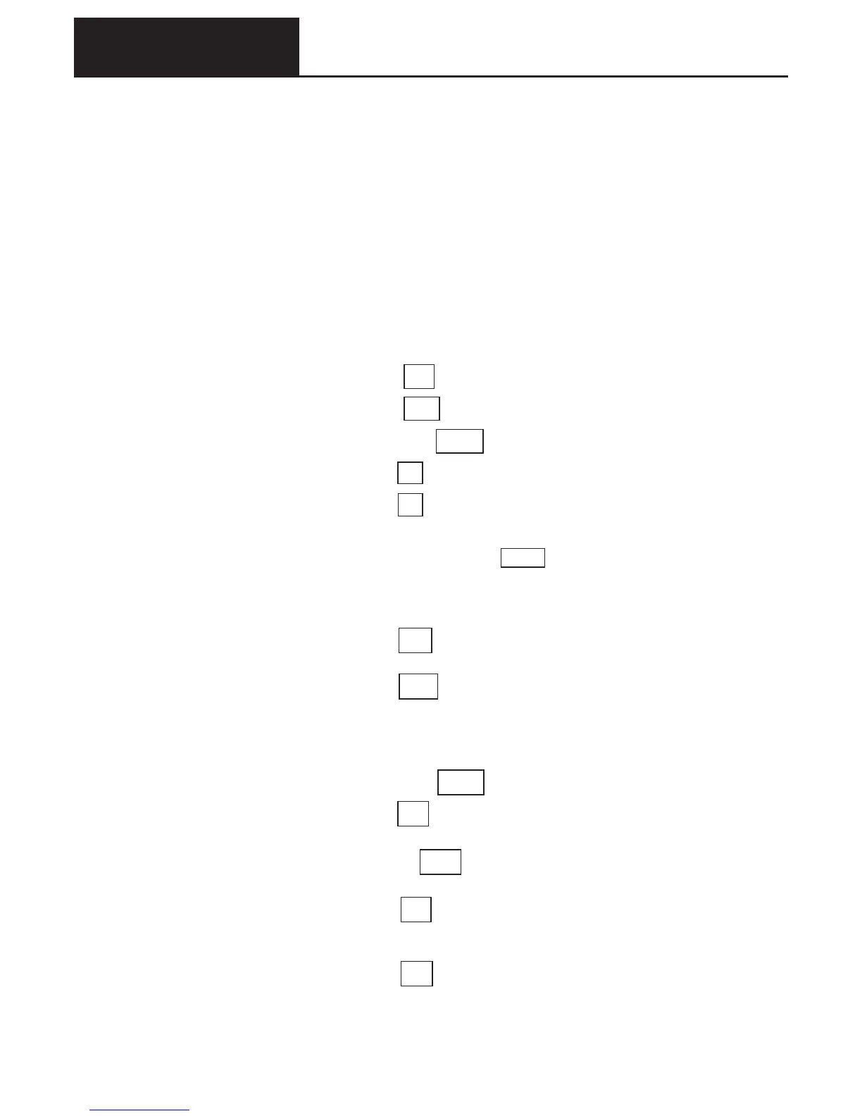
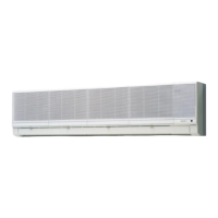
Earthquake resistance evaluation of
SGP-E90J2GU2(10 HP outdoor unit)
The earthquake resistance rank is common use, so the design horizontal earthquake factor K
H
is 1.0G.
(*K
H
= 1.0 is for installation on a roof. For installation on the ground K
H
= 0.4)
Refer to Item (3) for the position of the center of gravity of the equipment
Foundation bolts
• N
•
•
umber of bolts = 4
• Bolt diameter M12
*If as a result of the calculation this is not acceptable, change the conditions and re-calculate.
Example of evaluation by calculation
Foundation bolt conditions
Total no. of bolts(N
) N =㩷㩷 4㩷 ………..current models have 4 bolts
bolt diameter(D
) D =㩷㩷 12 mm ………..for M12 bolts
bolt cross-sectional area(A
) A = D
2
/4 =㩷 113 mm
2
bolts on one side䋺short direction(n
1
) n
1
=㩷 2㩷㩷………..current models have 2 bolts
㩷㩷㩷㩷㩷㩷 long direction(n
2
) n
2
=㩷 2㩷㩷………..current models have 2 bolts
The installation method is “embedded J type, JA type bolts”, on a slab 12cm thick.
Foundation bolt allowable short term tensile load(T
a
) ………..T
a
=㩷 11,760㩷 N
(It is also acceptable to decide the installation method after completing the calculation
)
Calculation
Design horizontal magnitude(K
H
) K
H
=㩷 1.0㩷㩷………..installation location:K
H
on roof: 1.0
㩷㩷㩷㩷㩷㩷㩷㩷㩷㩷㩷㩷㩷㩷㩷㩷㩷㩷㩷㩷㩷㩷㩷㩷㩷㩷㩷㩷㩷㩷㩷㩷㩷㩷㩷㩷㩷㩷㩷㩷㩷 㩷㩷on ground:0.4
Operating load(W) W =㩷 6,566㩷 N ……….. 70 type:6,860
(=operating mass×9.8
) 90 type:7,056
120 type:9,310
150 type:9,310
190 type:9,604
Horizontal earthquake force(F
H
) F
H
= K
H
䊶W=㩷㩷7,056 N
㩷㩷 㩷 Height of center of gravity(h
) h
G
=㩷 700 mm ………..70, 90 type :700
120, 150, 190 type :720
Vertical earthquake force(F
V
) F
V
=F
H
/2=㩷 3,528 N
Distance from center of gravity to bolt
Short direction(l
G1
) l
G1
=㩷㩷485 㩷 mm㩷 ………..70, 90 type :485
120, 150 type :495
190 type :475
Long direction(l
G2
) l
G2
=㩷㩷515 㩷 mm㩷 ……….. 70, 90 type :515
120, 150, 190 type :525
1
1
2
2
3
π
7. Center of gravity position and earthquake resistant design