Design
D - 34
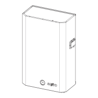
Notes‚
1.These are short term allowable pull out loads for bolts embedded
in as shown in the diagram above and with Fc
1
=11.8N/mm
2
,
Fc
2
=17.6N/mm
2
, W=100mm.
2.When the dimensions differ from the above diagram, or if the
concrete design characteristic strength differs, then the pull out
load may be calculated in accordance with the formulae for bolts
on a strong foundation, on the left. However, the allowable pull
out strength of one bolt may not exceed 11,760N.
3.It is desirable that ‚L 6d. The parts indicated by "-" in the above
table are not desirable.
4.For box dimensions with W less than or equal to 150mm, the
above table may be used.
5.If type 1 or type 2 lightweight concrete is used, allow 10% margin.
The short term allowable pull out load of a bolt is obtained from the
following formula. However, if the shear stress in the bolt exceeds
44.1N/mm2 (for SS400), bolt strength verification must be carried out,
and verification that the allowable tensile stresses are not exceeded
must also be carried out.
For Fc
1
Fc
2
...(a)
For Fc
1
>Fc
2
(e.g., non-shrink mortar, etc.)
...(b)
Here,
Ta : Foundation bolt short term pull out allowable load (N)
L : Foundation bolt embedded length (mm)
Fc
1 :
Characteristic design strength of the backfill mortar (N/mm
2
)
Fc
2 :
Design characteristic strength of the surrounding concrete
(N/mm
2
).
Normally, Fc
1
=11.8N/mm
2
Fc
2
=17.6N/mm
2
are used.
W : Box dimension of the boxed out foundation bolt
(100mm W 150mm),
For a rectangular shape, use the smallest dimension.
However, the internal surfaces of the box must be sufficiently
roughened.
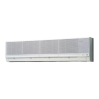
For foundation bolts positioned in the corner or near the edge of the
foundation, the short term allowable pull out strength shall be taken to
be either of the values from formulae c and (d) or (e) and (f).
1) for Fc
1
Fc
2
, L h
2) for Fc
1
Fc
2
, L>h
3) for Fc
1
>Fc
2
, L h
4) for Fc
1
>Fc
2
, L>h
Here,
h : Foundation plinth height (mm)
A : External dimension of the box out foundation bolt (mm)
Notes‚
1.It is desirable that L 6d (d=nominal diameter of foundation bolt)
2.If type 1 or type 2 lightweight concrete is used, allow 10% margin.
Installation location: a) Solid foundations b) Upper surface of normal floor slab c) Bottom surface of normal ceiling slab, concrete wall surface
Notes‚
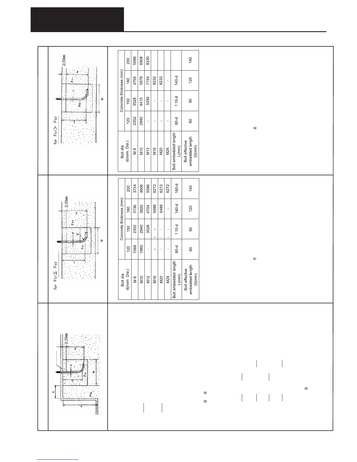
1.These are short term allowable pull out loads for bolts embedded in
as shown in the diagram above and with Fc
1
=20.6N/mm
2
,
Fc
2
=17.6N/mm
2
, W=100mm.
2.When the dimensions differ from the above diagram, or if the
concrete design characteristic strength differs, then the pull out
load may be calculated in accordance with the formulae for bolts
on a strong foundation, on the left. However, the allowable pull out
strength of one bolt may not exceed 11,760N.
3.It is desirable that ‚ L 6d. The parts indicated by "-" in the above
table are not desirable.
4.For box dimensions with W less than or equal to 150mm, the above
table may be used.
5.If type 1 or type 2 lightweight concrete is used, allow 10% margin.
Ta=
π
.
L
.
W
80
Fc
1
Ta=
π
.
L
.
W
80
Fc
2
Ta= π
.
L
.
W
80
Fc
1
10
A
Ta=
π
.
L
.
W
80
Fc
2
10
A
Ta=
π
.
L
.
W
.
(L - h + h)
80
Fc
1
10
A
Ta=
π
.
L
.
W
.
(L - h + h)
80
Fc
2
10
A
(5)
Allowable pull out load of boxed out L type, LA type bolts(Boxed out types are not normally used for the bottom of ceiling slabs or the surface of walls)
Short term pull out load (N) Long term allowable pull out load (N)
..(c)
..(d)
..(e)
..(f)
Mortar finish
7. Center of gravity position and earthquake resistant design