Do you have a question about the Sanyo SPW-T253GH56 and is the answer not in the manual?
Guidance on effectively navigating and utilizing the service manual's sections for optimal understanding and troubleshooting.
Detailed technical specifications for various indoor and outdoor unit models, including performance and electrical ratings.
Technical details of key components within both indoor and outdoor units, such as motors, compressors, and heat exchangers.
Specifications for auxiliary components like power transformers, thermistors, relays, and solenoid valves used in the air conditioning system.
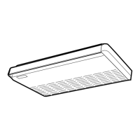
Provides physical dimensions and layout diagrams for indoor and outdoor units, crucial for installation and space planning.
Illustrates the refrigerant circulation path for both cooling and heating cycles, detailing component interactions.
Defines the environmental temperature limits for efficient cooling and heating operation of the air conditioning unit.
Explains how the system manages room temperature by controlling compressor and fan operations based on sensor readings.
Describes the mechanism to prevent cold air discharge during heating by managing indoor fan speed until coils warm up.
Details how the indoor fan speed automatically adjusts based on room temperature in cooling and heating modes.
Explains the automatic adjustment of the outdoor fan speed based on ambient temperature for optimized performance.
Outlines the system's protection against indoor coil freezing by regulating refrigerant flow and compressor operation.
Describes how condensing temperature is managed by controlling outdoor fan speed and refrigerant flow based on outdoor coil temperature.
Explains the function that prevents the air conditioner from overloading during heating operation to protect components.
Details the system's method to prevent compressor burnout by monitoring and controlling discharge gas temperature.
Explains how the unit automatically switches between cooling and heating modes based on temperature differentials.
Describes the defrost cycle operation to remove frost from the outdoor coil, ensuring efficient heating.
Explains the function of the 4-way valve in directing refrigerant flow for cooling and heating modes.
Details the unit's ability to resume operation automatically after a power failure, preserving settings.
Describes the function and precise control capability of the electronic valve for managing refrigerant flow.
Provides temperature ranges for compressor discharge gas under various operating conditions for troubleshooting.
Explains the circuit that monitors compressor current to prevent damage from overcurrent or locked rotor conditions.
Details the dehumidification mode, which removes moisture while minimizing temperature reduction using low fan speed.
Explains the control of the auto-flap for directing airflow in multiple steps across different operating modes.
Describes the control logic for the electronic refrigerant valve, including fuzzy control for optimal flow rate.
Details the voltage monitoring function that issues an alarm to protect components from abnormal voltage levels.
Provides wiring diagrams and schematic representations for the indoor unit's electrical system.
Offers detailed wiring diagrams and schematic representations for the outdoor unit's electrical system.
Guides users through diagnosing and resolving common problems using flow charts, alarm messages, and LED indicators.
Provides detailed procedures for testing electrical components, including resistance measurements and continuity checks.
| Cooling Capacity | 2.5 kW |
|---|---|
| Heating Capacity | 3.2 kW |
| Power Supply | 220-240V, 50Hz |
| Refrigerant | R410A |
| Weight (Indoor) | 9 kg |
| Type | Split System |
| Noise Level (Outdoor) | 50 dB |