Do you have a question about the Sanyo SR41XC and is the answer not in the manual?
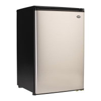
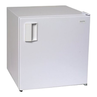
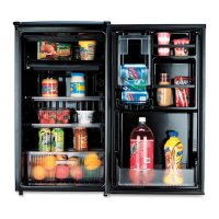
Details about the refrigerator's capacity, dimensions, and components.
Lists of main parts and compressor resistance values for different voltages.
Graph showing temperature pull-down performance under specified conditions.
Instructions for making ice using the clear ice system.
Procedure for removing ice from the clear ice system trays.
Guidance on storing the made ice.
Instructions for using the rapid-freezing function.
Instructions for using the deep-freezing function.
Explanation of the deodorization system and its operation.
Explanation of ozone properties and its applications in the refrigerator.
Description of how the ozone system works to eliminate odors.
Compares ozone system to others and addresses safety aspects.
Electrical diagram of the deodorizing system.
Details on voltage, capacity, and purpose of various heaters.
Equivalent circuit diagram of the refrigerator's electrical system.
Diagrams showing the physical positions of PCB connectors.
Detailed descriptions of connectors CN1, CN2, and CN3.
Details for connectors CN4, CN5, CN6, CN7, and CN101.
Steps to diagnose compressor and cooling performance issues.
Diagnosing and resolving defrost system problems.
Troubleshooting for non-lighting LEDs on the control panel.
Procedures for replacing sensors and components in freezing compartments.
Accessing and replacing parts around the evaporator, doors, and internal compartments.
Procedures for accessing the main PCB, compressor, and condenser.
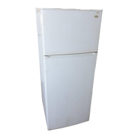
| Installation | Freestanding |
|---|---|
| Energy Efficiency Class | A |
| Color | White |
| Total Net Capacity | 14.6 cu ft |
| Fridge Net Capacity | 10.6 cu ft |
| Freezer Net Capacity | 4.0 cu ft |
| Total Capacity | 14.6 cu ft |
| Refrigerator Capacity | 10.6 cu ft |
| Freezer Capacity | 4.0 cu ft |