Do you have a question about the Sanyo TRC-7060 and is the answer not in the manual?
General precautions and cleaning advice before starting mechanism adjustments.
Lists the tools and materials needed for mechanism adjustments.
Procedure to adjust the clearance for the rewind solenoid.
Procedure to adjust the clearance for the play solenoid.
Steps to measure and adjust the take-up torque of the reel.
Procedure to adjust the clearance between the brake and take-up reel.
Steps to adjust the clearances for the flywheel and its support.
Procedure to adjust the cassette switch position for proper detection.
Guidance on replacing heads and adjusting azimuth for optimal audio output.
Steps for adjusting the motor speed using a test tape and frequency counter.
Specifies the required torques for play, fast forward, and rewind modes.
Lists parts related to packaging, accessories, and manuals.
Lists electrical components like speakers and connectors.
Lists components for the amplifier printed wiring board.
Lists components for the unit's cabinet and chassis assembly.
Lists various screws and fasteners used in the assembly.
Lists components for the indicator printed wiring board.
Lists components for the erase LED printed wiring board.
Block diagram for the pre-amplifier IC, showing its functions.
Block diagram for the cue tone detection IC and its inputs/outputs.
Block diagram for the remote control IC, detailing its inputs and outputs.
Block diagram for the motor control IC, showing its internal structure.
Explains the power supply circuit and its voltage distribution to different parts.
Describes the signal path and components involved in the playback function.
Details the operation of the circuit that detects cue tones for auto-stop functions.
Explains the generation and emission of alarm signals for various conditions.
Describes the circuit responsible for the backspace operation.
Explains how the foot control and remote signals are processed.
Wiring connections for the indicator printed wiring board.
Wiring connections for the erase LED component.
Wiring connections for the main printed circuit board.
Wiring connections for the amplifier printed wiring board.
| Brand | Sanyo |
|---|---|
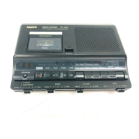
| Model | TRC-7060 |
| Power Source | Batteries or AC Adapter |
| Microphone Input | Yes |
| Headphone Jack | Yes |
| Speaker | Built-in |
| Auto Stop | Yes |
| Recording Function | Yes, built-in microphone |
| Type | Portable Cassette Player/Recorder |