Do you have a question about the Sanyo TRC6100 and is the answer not in the manual?
Instructions for safely removing the bottom cabinet cover.
Procedure for detaching the top cabinet cover from the unit.
Steps to remove the main frame, including related buttons.
Guide for detaching the amplifier's flexible printed circuit board.
Important notes before adjustment and required tools and equipment.
Setting switches and controls before performing electrical adjustments.
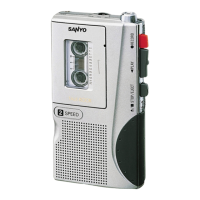
| Brand | Sanyo |
|---|---|
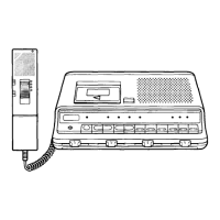
| Model | TRC6100 |
| Category | Microcassette Recorder |
| Language | English |