Do you have a question about the Sanyo V3622 and is the answer not in the manual?
Electrical safety, qualified electrician, proper connections, grounding.
Safe lifting and moving procedures for units to prevent injury.
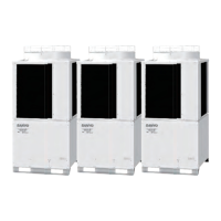
Mounting, insulation, and foundation for outdoor units.
Flare method, lubricant, torque wrench, leak checks.
Power off, keep clear of moving parts, site cleanup.
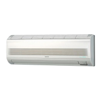
Performance, electrical ratings, features, dimensions, weight for both units.
Specs for indoor and outdoor unit components like motors, capacitors, etc.
Specs for transformers, thermostats, switches, contactors.
Charts showing operating current vs. ambient temp. and indoor temp.
Charts showing pressure vs. ambient temp. and indoor temp.
How the system cycles compressor based on room temp. sensor.
Compressor shut-off below 23°F coil temp., turn-on above 50°F.
Automatic fan speed adjustment based on outdoor air temperature.
Visual representation of the electrical connections between components.
Detailed wiring diagrams for the Printed Circuit Board assemblies.
Initial checks for power supply, inter-unit wiring, and connections.
Steps to diagnose why the unit fails to start, including circuit breaker and fuse checks.
Diagnosis for circuit breaker tripping, including ground faults and short circuits.
Diagnosing short circuits causing breaker trips, checking motor windings.
Steps for when neither unit powers on, checking power supply, fuses, and transformers.
Verifying operation of control switches and PCB for the control unit.
Measuring secondary winding resistance of the transformer.
Checking continuity and conditions related to the high pressure switch.
Troubleshooting steps for when only the indoor fan fails to run.
Troubleshooting steps for when only the outdoor fan fails to run.
Troubleshooting steps for when only the compressor fails to run.
Steps to identify and resolve poor cooling performance.
Steps to identify and resolve excessive cooling issues.
Procedure to measure insulation resistance of wires, units, and parts.
How to check fuse continuity using a multimeter.
Procedure for testing motor capacitor health.
Testing continuity of the operation switch terminals.
Testing continuity of the fan speed selector terminals.
Testing continuity of the auto deflector switch terminals.
Visual identification of the freeze protection thermostat.
Visual identification of the high pressure switch.
Visual identification of the PTC thermistor.
Visual identification of the electro-magnetic contactor.
Visual identification of the thermostat.
| Brand | Sanyo |
|---|---|
| Model | V3622 |
| Category | Air Conditioner |
| Language | English |