Follow the steps below to connect each cable firmly to the one-touch connector.
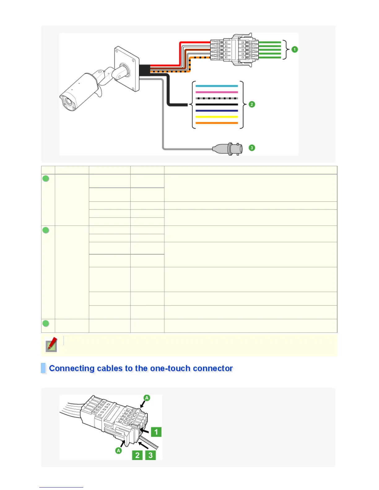
Shape Color Signal Name Use
1
One-touch
connector
RED 24 VAC/12
VDC (+)
Used to connect the power supply.
WHITE 24 VAC/12
VDC (–)
BROWN COMMON Earth terminal
GRAY RS485 (A) Used to connect the system controller or other external system component.
For connection, use cables with 22AWG wire or thicker.
ORANGE/BLACK RS485 (B)
2
Individual
cables
SKYBLUE UTP (+) Use these twisted pair cables to output the video signal to an external device.
PINK UTP (–)
GRAY/BLACK ALARM IN 1 Used to connect alarm switch, infrared sensor, or other external devices.
To automatically switch between the color and black/white modes, select
[DAY/NIGHT], choose the “COLOR” mode, and then set the “EXT ALARM” to
an appropriate input level.
BLACK ALARM IN 2
BLUE ALARM OUT Used to connect a buzzer, lamp, video recorder, or other peripheral device.
To control the alarm output externally from a remote location, on the ALARM
OUT screen, select [OUTPUT] and choose “REMOTE.”.
YELLOW FOCUS Used to adjust the camera focus by external voltage control.
DC ± (6 to 12 V), +: FAR/-: NEAR
ORANGE ZOOM Used to adjust the camera zoom by external voltage control.
DC ± (6 to 12 V), +: WIDE/-: TELE
3
BNC
connector
COAXIAL CABLE VIDEO OUT Used to connect to the VIDEO IN connector of your monitor.
For the cable type, see the “cable label” attached to the cable bundle.
2 / 100
 Loading...