SERVICE MANUAL
Contents
1. OUTLINE OF CIRCUIT DESCRIPTION ............................... 3
2. DISASSEMBLY ................................................................... 12
3. ELECTRICAL ADJUSTMENT ............................................. 18
4. USB STORAGE INFORMATION REGISTRATION ............ 24
5. TROUBLESHOOTING GUIDE............................................ 25
6. PARTS LIST........................................................................ 26
CIRCUIT DIAGRAMS & PRINTED WIRING BOARDS........... C1
CAUTION : Danger of explosion if battery is incorrectly replaced.
Replace only with the same or equivalent type recommended by the
manufacturer.
Discard used batteries according to the manufacturer’s instructions.
NOTE : 1. Parts order must contain model number, part number, and description.
2. Substitute parts may be supplied as the service parts.
3. N. S. P. : Not available as service parts.
Design and specification are subject to change without notice.
SG314/U, EX, GX, U2, EX2, GX2, U3, EX3, GX3, U4 (R)
REFERENCE No. SM5310773
FILE NO.
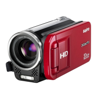
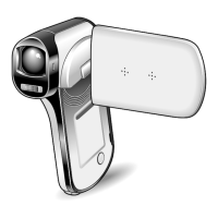
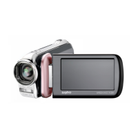
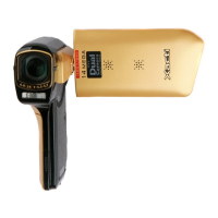
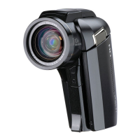
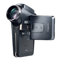
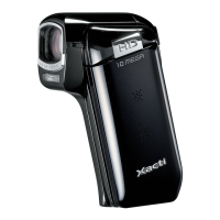
Dual Camera
RoHS
•This product does not contain any hazardous substances prohibited by the RoHS
Directive.
WARNING
•You are requested to use RoHS compliant parts for maintenance or repair.
•You are requested to use lead-free solder.
(This product has been manufactured using lead-free solder. Be sure to follow the
warning given on page 2 when carrying out repair work.)
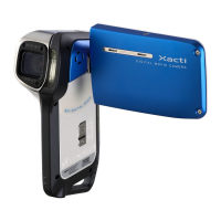
VPC-TH1
(Product Code : 168 173 02)
(U.S.A.) (Canada) (Taiwan) (General)
VPC-TH1EX
(Product Code : 168 173 03)
(Europe) (U.K.) (South America)
(China) (Australia) (Hong Kong)
(Russia) (Middle East) (Africa)
(General) (Korea) (Taiwan)
VPC-TH1GX
(Product Code : 168 173 04)
(South America) (China)
(Australia) (Hong Kong)
(General) (Korea) (Taiwan)
VPC-TH1R
(Product Code : 168 173 06)
(U.S.A.) (Canada) (Taiwan) (General)
VPC-TH1EXR
(Product Code : 168 173 07)
(Europe) (U.K.) (South America)
(China) (Australia) (Hong Kong)
(Russia) (Middle East) (Africa)
(General) (Korea) (Taiwan)
VPC-TH1GXR
(Product Code : 168 173 08)
(South America) (China)
(Australia) (Hong Kong)
(General) (Korea) (Taiwan)
VPC-TH1BL
(Product Code : 168 173 10)
(U.S.A.) (Canada) (Taiwan) (General)
VPC-TH1EXBL
(Product Code : 168 173 11)
(Europe) (U.K.) (South America)
(China) (Australia) (Hong Kong)
(Russia) (Middle East) (Africa)
(General) (Korea) (Taiwan)
VPC-TH1GXBL
(Product Code : 168 173 12)
(South America) (China)
(Australia) (Hong Kong)
(General) (Korea) (Taiwan)
VPC-ZH1R
(Product Code : 168 173 13)
(U.S.A.) (Canada)