Do you have a question about the SANYU SY2000 Series and is the answer not in the manual?
Provides a basic wiring diagram for the inverter and its connections to external components.
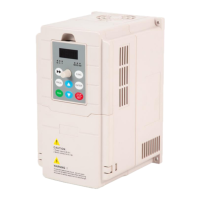
Describes the symbols, names, and functions of the indicators on the inverter's operation panel.
Lists monitoring parameters, their setting ranges, default values, and amendment status for inverter operation.
Details fault codes, their descriptions, causes, and recommended solutions for troubleshooting inverter issues.
Summarizes basic operating parameters, including their codes, descriptions, setting ranges, and default values.
Details auxiliary operating parameters, covering starting methods, DC braking, and speed settings.
Describes parameters related to analog inputs (AVI, ACI) and outputs (AO) for controlling inverter functions.
Explains the various functions that can be assigned to input terminals X1 through X6 for control.
Configures the PID control function, including adjustment characteristics and input channel selection.
Sets the target value for PID control, allowing manual input via the operation keyboard.
Covers parameters for setting motor characteristics like rated voltage, current, speed, frequency, and resistance.
Sets the unique address for the inverter on a communication network, with 0 being the broadcast address.
Configures communication settings like baud rate, data format, and response mode for Modbus communication.
Defines modes for counting and timing operations, including single/cycle counts and various timing arrival methods.
Sets the lower limit frequency for the external pulse input X5, defining the operational range.
Selects which parameter is displayed on the main monitoring interface for real-time operation observation.
Allows restoring factory settings or clearing fault records, returning the inverter to its default state.
Describes the RTU mode and data frame format for Modbus communication, including bit sequence and error checking.
Explains the function codes used for reading (03H) and writing (06H) registers in communication.
Details parameter addresses and their corresponding data explanations for communication commands and frequency settings.
Specifies parameters for reading inverter status like frequency, voltage, current, and temperature.
Provides a description of fault codes, including abnormality, module failure, overvoltage, and overcurrent.
Outlines daily checks for the inverter and motor, including sound, vibration, temperature, and load current.
Details periodic inspections of terminals, wiring, and components, along with cleaning and insulation testing procedures.
Provides a table of standard replacement years for key electronic components like cooling fans and capacitors.
| Cooling Method | Forced Air Cooling |
|---|---|
| Communication Interface | RS485 |
| Ambient Temperature | -10°C to +40°C |
| Control Method | PWM |
| Protection | Overvoltage |
| Protection Features | Overload |
| Relative Humidity | <90% (no condensation) |
| Altitude | <1000m |