User Manual & Datasheet V 2.3
7 Mechanical Specifications
Please refer to Table 3 for Mechanical Specifications.
PARAMETER VALUE
Housing
• SCUTE: Pressure die-cast aluminium weatherproof
(Rating IP-68)
• FP2C: Cast aluminium, weatherproof & flameproof,
powder coated, suitable for Gas Groups IIA, IIB & IIC
as per IS-2148
Electrical Connector PG-13.5, 1/2" BSP DC Glands, 1/2” NPT DC Glands
Mounting
• Screwed - 1”/1 1/2” BSP/NTP(M)
• Flanged - As per your specifications
• Material - MS (Plated), SS
Sensing Fork SS 316
Extension Pipe GI (Galvanized Iron) / SS-304 / SS -316
Table 3: Mechanical Specifications
8 Installation & Handling Guidelines
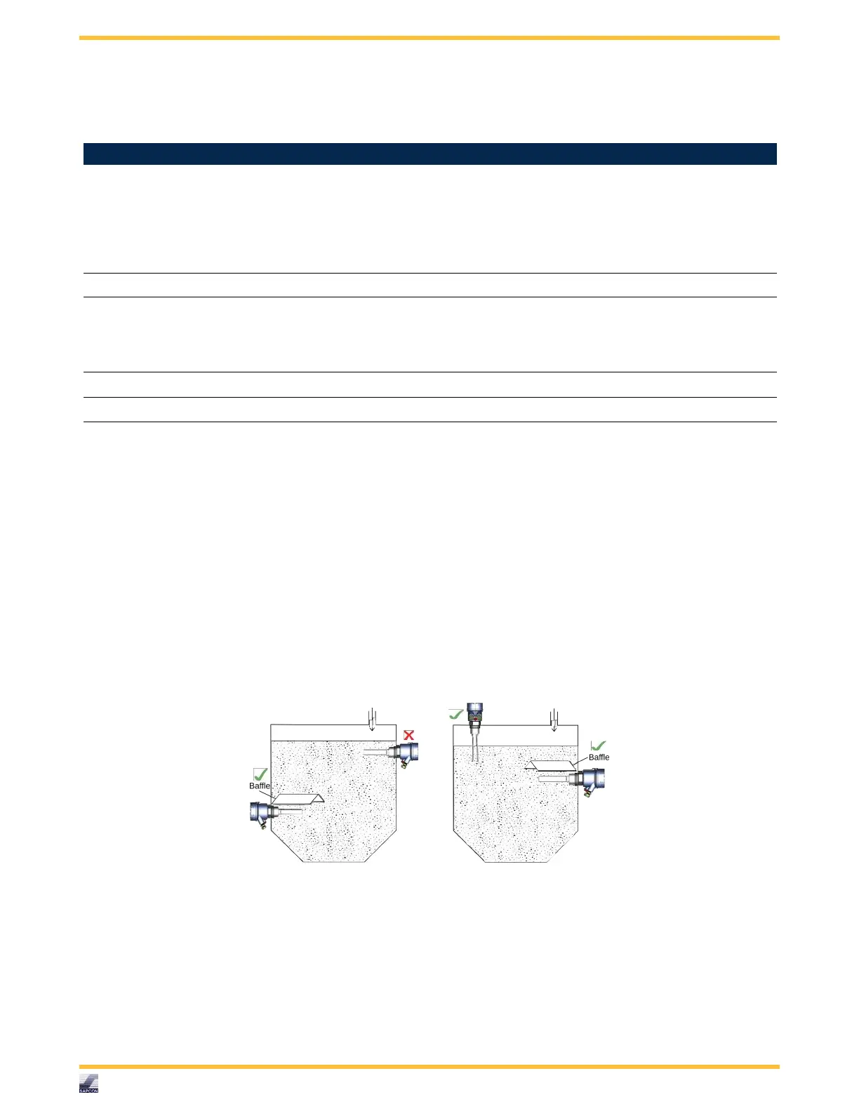
The fork should be installed in horizontal or vertical position. The following image displays different allowable installation
positions. Observe that when installed directly under the material inlet source, a canopy called baffle of appropriate strength
and size should be welded right above the fork as shown.
While installing the instrument, please take care of the following points:
• The instrument shouldn’t block the material filling inlet.
• Secure the cover of housing tightly. Tighten the cable glands.
• For side-mounting, provide a baffle to prevent the application material from falling on the fork.
Please refer to Figure 3.
Figure 3: Correct Side Mounting
• When handling forks, do not lift them using their tines. Please see Figure 4.
• The tines should not be bent and neither should their dimensions be altered. Deforming the shape of the tines may
interfere with the fork’s operating frequency. Please see Figure 4.
• Make all electrical connections as instructed in the manual. Don’t power on the device before verifying the connections.
• To prevent the ingress of moisture and water seepage in side mounting position, the cable entries should always point
downwards.
Sapcon Instruments Pvt.Ltd.
R
7