12
13 14
34
The Sapling Company, Inc.
1633 Republic Road
Huntingdon Valley, PA 19006
USA
P. (+1) 215.322.6063
F. (+1) 215.322.8498
www.sapling-inc.com
Flag Mount Installation - Round SlimLine/Aluminum Clock
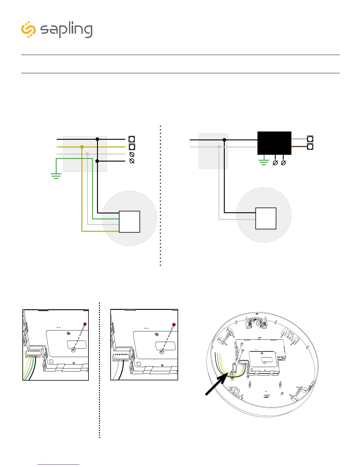
12) Attach the signal and power wires from your kit to the wires you threaded through the pole. Consult
the diagrams below for additional help, or see the sections of this manual labeled “3-Wire Synchronous
(Sync-Wire) Communication Wiring Information” or “2-Wire Digital Communication Wiring Information”
for additional details, depending on your system.
13) Remove the gearbox pin, then attach a
power connector to the port on the side of
the movement.
14) Lay any excess wiring across the strain relief
base, then attach the strain relief to the clock with
the two #6-19x7/16 screws. The strain relief should
be tight enough to prevent the wire from sliding.
2-Wire Digital3-Wire Sync
Yellow
Black
White
Black
White
Yellow
27/24
26/23
To next
clock
Power
Common
Master Clock
CLOCK 1
Gang
Box
Green
Green
Ground
Black
White
Black
White
18
19
To next
clock
Master Clock
CLOCK 1
Gang
Box
115VAC or
230VAC
A2/B2/C2
A1/B1/C1
Input A
Input B
Converter
Box
Yellow
White
Green
Black
White
Black
3-Wire Sync 2-Wire Digital