Sargent Electrical Services Ltd. Copyright 2005
Issue 03 Page 2 of 11 12 May 2005
3 POWER SUPPLY UNIT – SYSTEM OPERATION
3.1 INTRODUCTION
For the safe operation of all electrical equipment within your Leisure Vehicle it is important that you
read and fully understand these instructions. If you are unsure of any point please contact your dealer
/ distributor for advice before use.
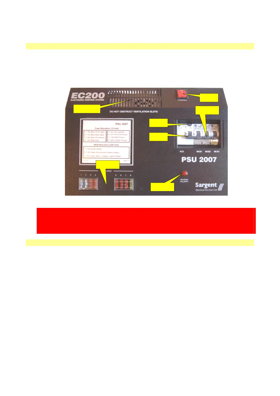
The following diagram shows the PSU2007 layout.
POWER
SWITCH
RCD TEST
BUTTON
RCD
SWITCH
MCB
SWITCHES
POLARITY
INDICATOR
DC SUPPLY
FUSES
CHARGER
VENTILATION
WARNING
Under heavy loads the PSU2007 case will become hot. ALWAYS ensure the ventilation slots have a
clear flow of air. Do not place combustible materials against / adjacent to the PSU2007. The PSU will
shutdown if overheated and will restart automatically when cool.
3.2 MAINS CONNECTION
For your safety it is IMPORTANT that you follow these connections instructions each time your Leisure
Vehicle is connected to a mains supply.
A) Ensure suitability of the Mains Supply. Your Leisure Vehicle should only be connected to an
approved supply that meets the requirements of BS7671. In most cases the site warden will hold
information regarding suitability of supply. If using a generator you also need to comply with the
requirements / instructions supplied with the generator.
B) Switch the PSU2007 internal Charger unit OFF. Locate the red ‘Charger’ power switch on the
PSU2007 and ensure the switch is in the OFF (0) position before connection to the mains supply.
C) Connect the Hook-up Lead. Firstly connect the supplied hook-up lead (orange cable with blue
connectors) to the Leisure Vehicle and then connect to the mains supply.
D) Check Residual Current Device operation. Locate the RCD within the PSU2007 and ensure the
RCD is switched on (lever in up position). Press the ‘TEST’ button and confirm that the RCD is
turned off (lever in down position). Switch the RCD back to the on position (lever in up position). If
the test button failed to operate the RCD see section 3.4.
E) Check correct Polarity. Locate the ‘Reverse Polarity’ indicator on the PSU2007 and ensure that
the indicator is NOT illuminated. If the indicator is illuminated see section 3.4.
F) Check Miniature Circuit Breakers. Locate the MCB’s within the PSU2007 (adjacent to the RCD)
and ensure they are all in the ON (up) position. If any MCB’s fail to latch in the on position see
section 3.4.
 Loading...