Do you have a question about the Sargent EC200 and is the answer not in the manual?
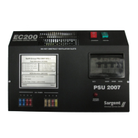
Overview of EC200 system components including PSU2007 and Digital Control Panel.
Instructions for safe operation of electrical equipment within a leisure vehicle.
Step-by-step guide for connecting the leisure vehicle to a mains supply safely.
Details on selecting, installing, removing, and servicing leisure vehicle batteries.
Troubleshooting guide for common faults like no output, with possible causes and fixes.
Troubleshooting common issues with the control panel, including display and functionality.
Diagram and description of the control panel's buttons and their functions.
Details of the control panel's reading menus, including battery status and water levels.
Guide to control panel settings, covering pump selection, clock, alarm, and event timers.
Explanation of warning messages displayed on the control panel, like low battery or system disabled.
Example of how to use the event timer to schedule 12v power on/off events.
Technical specifications of the EC200 system, including electrical inputs, outputs, and charger.
Physical dimensions and weight for the PSU2007 and Control Panel.
List of compliance standards and directives for the EC200 system.
Formal declaration by the manufacturer regarding compliance with directives.
Diagram showing 230V AC input and output connections to the PSU.
Diagrams for 12V DC signal inputs and outputs, with pin assignments.
The Sargent Electrical Services Ltd. EC200 Electronic Control System is a microprocessor-controlled digital system designed to provide a comprehensive control solution for various leisure vehicles. It allows users to manage equipment and access/modify system information through a user-friendly control panel featuring an alphanumeric liquid crystal display.
The EC200 system primarily consists of a Power Supply and Control Unit (PSU2007) and a Digital Control Panel. The PSU2007 integrates Mains 240V protection equipment, a 200-watt 12V charger/power supply, and 12V equipment power control/protection. The Digital Control Panel connects to the PSU2007 via a data cable, enabling user interaction.
Key functions include:
| Brand | Sargent |
|---|---|
| Model | EC200 |
| Category | Control Systems |
| Language | English |