Sargent Electrical Services Ltd. Copyright 2005
Issue 03 Page 6 of 11 12 May 2005
4 CONTROL PANEL OPERATION
4.1 Layout and Buttons
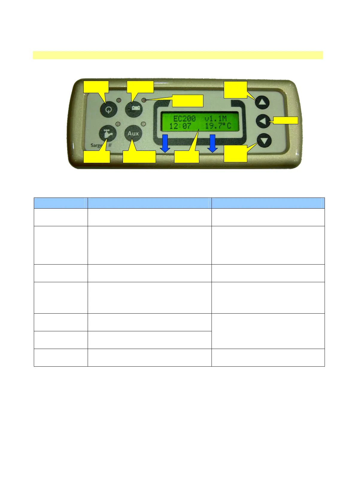
The following diagram shows the control panel layout.
POWER
ON / OFF
SCROLL
UP /
ADJUST
SELECT
AUXILIARY
ON / OFF
PUMP(S)
ON / OFF
BATTERY
SELECT
SCROLL
DOWN /
ADJUST
INDICATOR
LAMPS (x4)
2x16 LCD
DISPLAY
Note: to remove the decorative bezel, pull down and lift forward as indicated by the blue arrows.
Item Function Options / Notes
Power ON / OFF Use to turn the main power on and off
The adjacent LED is illuminated when
the power is ON
Battery SELECT
Use to select the Leisure or Vehicle battery
as the supply source
The adjacent LED is illuminated when
the VEHICLE battery is selected; by
default the Leisure battery is selected
and is indicated by the battery select
LED off.
Pump ON/ OFF
Use to turn the water pump(s) power on and
off (see section 4.3)
The adjacent LED is illuminated when
the pump power is ON
Aux ON / OFF
Use to turn the Auxiliary power on and off
(see manufacturers handbook for detail of
what items are operated by the auxiliary
function)
The adjacent LED is illuminated when
the auxiliary power is ON
Scroll UP ?
Use to scroll the display up (settings section
of the menu) (see section 4.3)
Scroll DOWN ?
Use to scroll the display down (readings
section of the menu) (see section 4.2)
Note: the menu screens operate in a
continuous loop, therefore you can use
either the UP or DOWN buttons to
move to any screen
Select ?
Use to select a menu item within the
settings section (see section 4.2 & 4.3)
Use to move to the next setting, when
entering alarm / event times
Note: the display backlight operated for approximately 6 seconds after any key press.
 Loading...