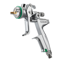
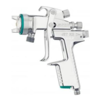
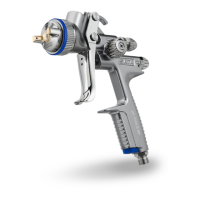
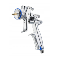
This document provides operating instructions for the SATAjet 4600 B RP/HVLP spray gun, a device designed for applying paints, lacquers, and other sprayable media using compressed air.
Function Description
The SATAjet 4600 B RP/HVLP is a spray gun used for professional painting applications. It operates by atomizing paint or other fluid media with compressed air, allowing for an even and controlled application on various surfaces. The gun features a handle, trigger, and a nozzle set comprising an air cap, fluid tip, and paint needle. Material flow and spray fan patterns (round/flat) can be adjusted for precise control. It also includes a ColorCode-System (CCS) for individual marking. The device is suitable for use in explosion-hazard areas classified as Ex-zone 1 and 2, provided specific safety guidelines are followed.
Important Technical Specifications
Recommended Spray Gun Inlet Pressure:
- RP: 2.0 - 2.2 bar (29 - 32 psi)
- HVLP: 2.0 bar (29 psi)
- Compliant: > 2.0 bar (air cap pressure > 0.7 bar) (> 29 psi, air cap pressure > 10 psi)
- Compliant legislation Lombardy/Italy: < 2.5 bar (air cap pressure < 1.0 bar) (< 35 psi, air cap pressure < 15 psi)
Recommended Spraying Distance:
- RP: 17 - 21 cm (6.7” - 8.3”)
- HVLP: 10 - 15 cm (3.9” - 5.9”)
- HVLP Lombardy/Italy: 10 - 15 cm (3.9” - 5.9”)
Max. Spray Gun Inlet Pressure: 10.0 bar (145 psi)
Air Consumption at 2.0 bar (29 psi) Spray Gun Inlet Pressure:
- RP: 300 Nl/min (10.6 cfm)
- HVLP: 430 Nl/min (15.2 cfm)
Max. Temperature of the Spray Medium: 50 °C (122 °F)
Weight (Standard Version):
- Without cup: 440 g (15.5 oz.)
- With 0.6 l RPS cup: 491 g (17.3 oz.)
- With 0.6 l reusable cup: 612 g (21.6 oz.)
- With 1.0 l aluminium reusable cup: 636 g (22.4 oz.)
- With 0.6 l RPS cup and digital gauge (with adam 2): 531 g (18.7 oz.)
Compressed Air Connection: 1/4" (external thread)
Capacity of PVC Gravity Flow Cup: 600 ml
Usage Features
The spray gun is designed for straightforward operation. Before use, all screws, especially the fluid tip [2-1] and locking screw [2-5], should be checked for tightness. The paint channel [2-6] should be rinsed with a suitable cleaning solution. The air cap can be adjusted for vertical [2-7] or horizontal [2-8] spray patterns. The paint strainer [2-9] and gravity flow cup [2-10] are then installed. The gravity flow cup should be filled to a maximum of 20 mm below the upper edge, closed with the lid [2-11], and the anti-drip device [2-12] inserted. The connection nipple [2-13] is screwed onto the air inlet, and the compressed air hose [2-14] is connected.
Adjusting the spray gun inlet pressure involves pulling the trigger fully and setting the pressure according to the recommended values in Chapter 2, using either a SATA adam 2 [3-1], a separate gauge with [3-2] or without [3-3] a control device, or by regulating pressure at the compressed air circuit [3-4]. When using methods [3-2], [3-3], and [3-4], the air micrometer [1-13] must be fully open and in a vertical position.
Material flow [4-1], [4-2], [4-3], [4-4] is adjusted with the material flow control screw [1-11]. Keeping this fully open minimizes wear on the fluid tip and paint needle. The spray fan pattern can be adjusted to a flat fan [5-1] (factory setting) or a round fan [5-2]. For painting, the trigger [6-1] is pulled fully, and the gun is guided [6-2] at the recommended spraying distance.
Maintenance Features
Regular cleaning and maintenance are crucial for the spray gun's longevity and performance.
Cleaning:
- Always disconnect the spray gun from the compressed air circuit before cleaning.
- Empty the spray gun and gravity flow cup completely, disposing of paint material properly.
- Disassemble and install components carefully using only the included special tools.
- Use neutral cleaning solutions (pH 6 to 8); avoid acids, lyes, bases, pickling agents, or other aggressive cleaning agents.
- Never soak the spray gun in cleaning solution, and ensure cleaning solution does not enter air passages.
- Clean drillings with SATA cleaning brushes or nozzle cleaning needles only.
- Use SATA-recommended spray gun washing machines, ensuring air passages are pressurized with clean compressed air and the nozzle head points downwards during cleaning.
- Remove the spray gun immediately after cleaning.
- Never use ultrasonic cleaning devices.
- After cleaning, blow dry the spray gun, material passages, air cap (including thread), and gravity flow cup with clean compressed air to prevent corrosion.
- Check the spray pattern after cleaning the nozzle set.
Maintenance:
- Disconnect the spray gun from the compressed air circuit before any maintenance work.
- Disassemble and install components carefully using only included special tools.
Replacing the Nozzle Set [7-1], [7-2], [7-3], [7-4], [7-5], [7-6]:
- The nozzle set includes the paint needle [7-1], air cap [7-2], and fluid tip [7-3], which are hand-adjusted for a perfect spray pattern.
- Always replace the complete nozzle set.
- Lubricate the paint needle [7-1] in the needle sealing area (approx. 3 cm before the needle sleeve, paint needle spring) and the threads of the material flow control screw [1-11].
- Adjust material flow after installation.
Replacing the Air Distribution Ring [7-1], [7-2], [7-3], [8-1], [8-2], [8-3], [7-4], [7-5], [7-6]:
- Remove the air distribution insert using only the SATA extraction tool.
- Avoid force to prevent damage to sealing surfaces.
- Check and clean sealing surfaces [8-2] after disassembly. If damaged, contact your SATA dealer.
- Align the new air distribution ring with the marking [8-3] (pin into drilling) and press in evenly.
- Adjust material flow after installation.
Replacing the Paint Needle Sealing [9-1], [9-2], [9-3]:
- Replace if paint material leaks from the self-tensioning paint needle packing.
- Remove the trigger [9-2].
- Check the paint needle for damage and replace the nozzle set if necessary.
- Adjust material flow after installation.
Replacing the Air Piston, Air Piston Spring, and Air Micrometer [10-1], [10-2], [10-3]:
- Disconnect the spray gun from the compressed air circuit.
- Replace if air leaks from the air cap or air micrometer when the trigger is not pulled.
- Grease the air micrometer sleeve with SATA high performance grease (Art. No. 47173) after disassembly.
- Insert the air piston and tighten the locking screw [10-1].
- Check the locking screw for tightness to prevent the air micrometer from shooting out.
- Adjust material flow after installation.
Replacing the Sealing (Air Side) [9-1], [9-2], [10-1], [10-2], [10-3], [10-4], [10-5]:
- Disconnect the spray gun from the compressed air circuit.
- Replace the self-adjusting sealing [10-5] if air leaks from under the trigger.
- Check and clean the air piston rod [10-4] after disassembly. Replace if damaged and grease with SATA high performance spray gun grease (Art. No. 48173). Observe correct installation order.
- Lubricate the air micrometer sleeve, insert with the air piston, and tighten the locking screw.
- Adjust material flow after installation.
- Check the locking screw for tightness to prevent the air micrometer from shooting out.
Replacing the CCS (ColorCode-System) [10-6]:
- The CCS can be exchanged for individual marking of the spray gun.
Replacing the Spindle of Round/Flat Fan Control [11-1], [11-2], [11-3]:
- Replace if air leaks from the fan control or if it malfunctions.
- Remove the old spindle [a] by removing screw [11-1] (Torx T20), knob [11-2], and unscrewing spindle [11-3] with a wrench (size 14).
- Clean any material or paint residues from the spindle pick-up with solvent.
- Install the new spindle [a, b] by screwing in spindle [11-3] and turning the spindle nut [11-3] to the 6 o'clock position with a wrench (size 6) [11-4].
- Position and assemble the control knob [c] by aligning knob [11-2] vertically and hand-tightening screw [11-1] (Torx T20) while holding the knob in position.