6 AOD-210 SATEL
4. Replace the cover.
5. Put the detector at the place of its future installation.
6. Check the level of signal received from the detector by the ABAX 2 / ABAX controller or
the INTEGRA 128-WRL control panel. If the signal level is lower than 40%, select another
place for installation. Sometimes, it is sufficient to shift the device ten or twenty
centimeters to obtain a considerable improvement in the signal quality.
The ARF-200 tester makes it possible to check the radio signal strength at the place of
future installation without having to put the detector there.
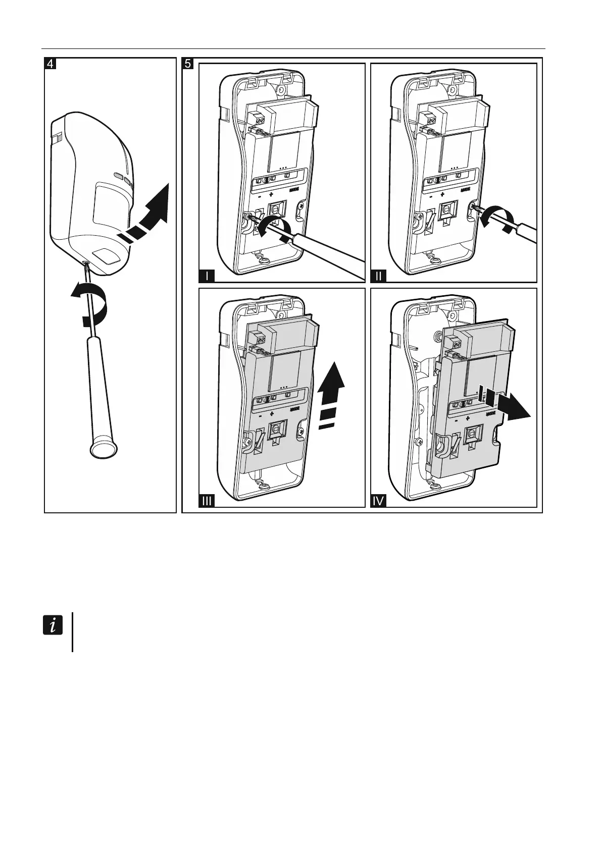
7. Remove the front cover (Fig. 4).
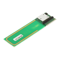
8. Remove the electronics module (Fig. 5).
9. If the detector is to be mounted on angle bracket or ball bracket, make a hole in the
enclosure base for the additional tamper switch cables.
10. Mount the enclosure base to the wall, to the angle bracket (see: “Angle bracket
mounting”) or to the ball bracket (see: “Ball bracket mounting”). The wall plugs (anchors)
delivered with the device are intended for concrete, brick, etc. For other types of surface
(drywall, styrofoam), use the appropriately selected wall plugs. In Figure 6 possible ways
of mounting the detector are shown.