4 AOD-210 SATEL
In response to the battery voltage drop below 2.75 V, sensitivity of sensors in the
detector is automatically lowered to eliminate false alarms.
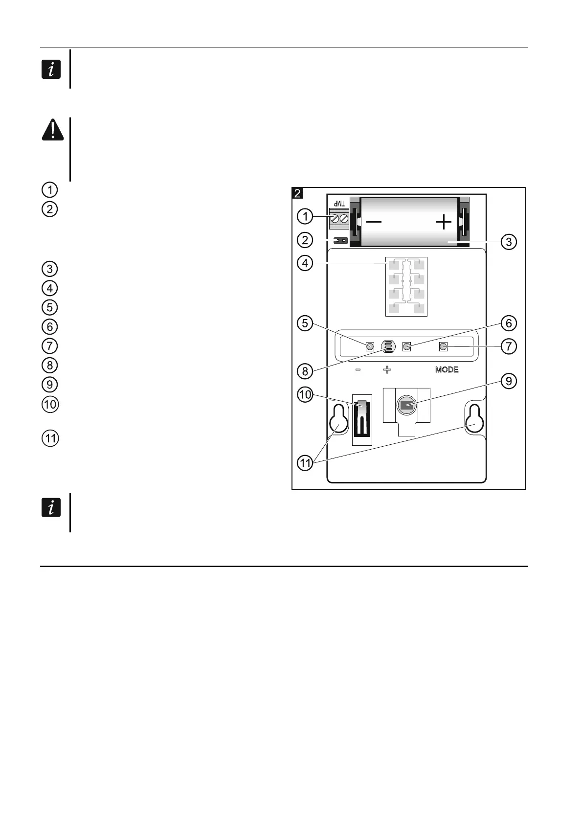
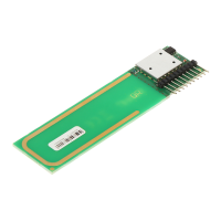
Electronics module
Do not remove the plastic cover from the circuit board to prevent damage to the
components located on the board.
Do not touch the pyroelectric sensor, so as not to soil it.
TMP terminals – tamper input (NC).
pins to enable/disable the tamper input. If
no additional tamper switch is connected
to the TMP terminals, jumper should be
placed across the pins.
CR123A lithium battery.
microwave sensor.
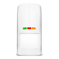
green LED.
red LED.
yellow LED.
dusk sensor.
PIR sensor (dual element pyrosensor).
tamper switch activated by cover
removal.
fixing screw holes.
On the other side of the electronic board is
a tamper switch activated by removing the
detector from the wall.
When mounting the detector on the angle or ball bracket, it is recommended to install
additional tamper switch.
3 Selecting a mounting location
Install the detector at the recommended height (Fig. 3-I).
If traffic nearby or objects moving out of the protected area cause an alarm, move the
detector slightly downwards or reduce the detector sensitivity (Fig. 3-II).
Install the detector so that the expected movement of an intruder will be across the
coverage pattern (Fig. 3-III).
Don’t install the detector closer than 3 meters from the moving objects (eg. tree branches,
bushes, laundry etc.) (Fig. 3-IV).
Don’t direct the detector on reflective surfaces or on fans or a heat sources (Fig. 3-V).