SATEL APD-200 5
Simultaneous operation of the detector by the ABAX 2 and ABAX controller /
INTEGRA 128-WRL alarm control panel is not possible.
4. Place the electronics module in the enclosure base and then move it up to lock it.
5. Replace the cover.
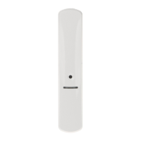
6. Put the detector at the place of its future installation.
7. Check the level of signal received from the detector by the ABAX 2 / ABAX controller or
the INTEGRA 128-WRL control panel. If the signal level is lower than 40%, select another
place for installation. Sometimes, it is sufficient to shift the device ten or twenty
centimeters to obtain a considerable improvement in the signal quality.
The ARF-200 tester makes it possible to check the radio signal strength at the place of
future installation without having to put the detector there.
8. Remove the front cover (Fig. 2) and remove the electronics module (Fig. 3).
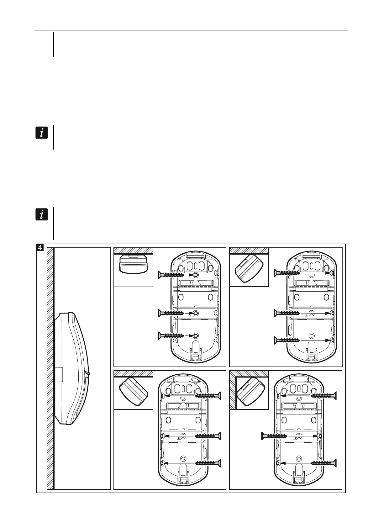
9. Make screw holes in the enclosure base.
10. Secure the enclosure base to the wall (Fig. 4) or the bracket fastened with screws to the
wall or ceiling (Fig. 5). The wall plugs (anchors) delivered with the device are intended for
concrete, brick, etc. For other types of surface (drywall, styrofoam), use the appropriately
selected wall plugs.
If the detector is to comply with the EN50131-2-2 requirements for Grade 2, do not
install it on the mounting bracket (if installed on the bracket, the detector will comply
with the standard requirements for Grade 1).