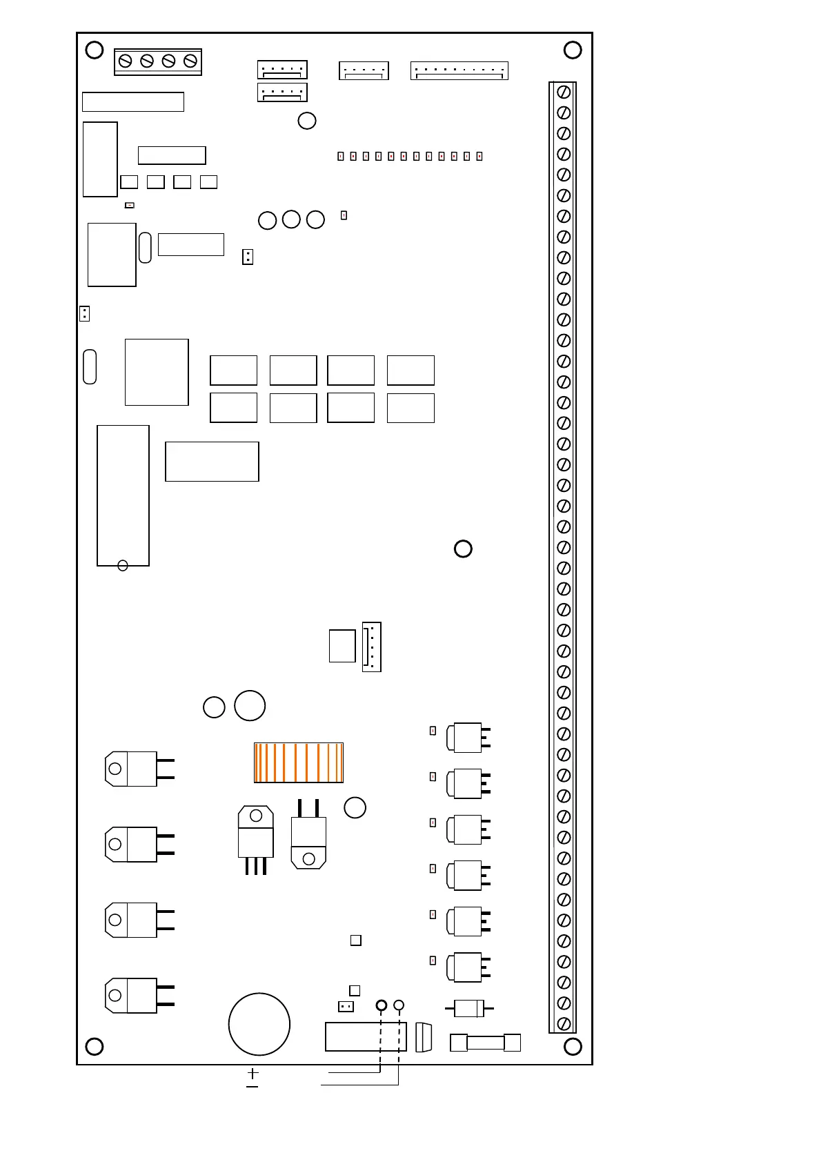
Fig. 12. The arrangement of units on the CA-64 control panel.
BOARD TERMINALS:
AC
-
module supply zones(20...24V AC)
Z1
to
Z16
-
zones lines
OUT1
to
OUT16
-
programmable outputs
+KPD, DTM, CKM
-
keypad bus
+EX1, DT1, CK1
-
first bus of expanders
+EX2, DT2, CK2
-
second bus of expanders
round
TIP, RING
-
outside telephone line
T-1, R-1
- inside telephone line (telephone set connection)
+12V
-
supply output
SYNT1, SYNT2
-
connectors for voice synthesizers
RS-232
- connector for service computer
BATTERY CHARGE
500mA 1000mA
RESET
R-1 T-1 RING TIP
5W 0.1ΩJ
T3.15A
DIALER
SYNT1 SYNT2
CHARGE
+12V
OUT5
OUT6
OUT7
OUT8
AC AC COM OUT1 COM OUT2 COM OUT3COM OUT4COM+KPD DTM CKM COM +EX1 DT1 CK1 COM +EX2 DT2 CK2 Z1 COM Z2 Z3 COM Z4 Z5 COM Z6 Z7 COM Z8 Z9 COM Z10 Z11 COM Z12 Z13 COM Z14 Z15
+12V
OUT9
OUT10
OUT11
OUT12
OUT13
OUT14
OUT15
OUT16
COM
MEMORY
SERIAL
PORT RS-232
RED
BLACK
BATTERY