CONTROL PANEL INSTALLATION
25
common electronic circuit breaker (limitation 3A), the presence of power supply
voltage is signalled by the sixth LED in the electronic circuit breaker block.
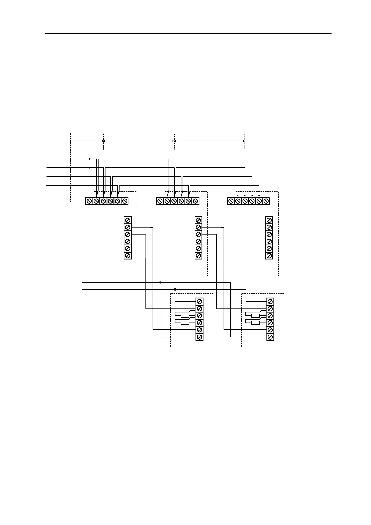
Modules may be connected with the use of a typical, non-screened cable used in
alarm systems (for example, DY8x0,5). Signals DTn, CKn and COM should be
contained in one cable (cannot be led through separate cables). For small distances
(up to 100 metres), when only modules are connected to the power supply cable, it is
permissible to connect some modules one after one (see Figure 16). Additional
equipment connected to the power supply source must be supplied through separate
cables (detectors connected to modules A and B).
Z 8
COM
Z 7
Z 6
COM
Z 5
CONTROL
+12V
+12V
+12VDATA CLK COM
COM
TMP
Z 8
COM
Z 7
Z 6
COM
Z 5
+12V
+12VDATA CLK COM TMP
Z 8
COM
Z 7
Z 6
COM
Z 5
+12V
+12VDATA CLK COM TMP
+Exn
DT n
CK n
COM
UP TO 100 mUP TO 100 mUP TO 100 m
+12 V
NO
C
TAMP
TAMP
GND
DETECTOR
+12 V
NO
C
TAMP
TAMP
GND
DETECTOR
EKSPANDER A EKSPANDER B EKSPANDER C
PANEL
Fig. 16. Correct connection of modules for small distances between the control panel
and modules, and way of detector connection.
NOTE:
Connection of fourth module after module C is not recommended when a
typical cable DY8x0,5 is used. The module connected in this way may be not
“seen” by the control panel. Resistance of cables at DTn and COM causes
that logic level “0” at the control panel input may be higher than the maximum
allowable level.
For large distances between the control panel and modules (up to 1000 metres),
modules should not be powered from the control panel, and DTn, CKn and COM
signals should use two-wire cable. Additionally, signals DTn, CKn and COM must be
in one cable. It is possible to connect several modules in parallel and connect them
to a single, common cable, through which the DTn, CKn and COM signals will be
connected (see Figure 17). For example, when the distance from the control panel to
the cabling node is 800 metres and the distance from the cabling node to the module
is less than 100 metres, it is possible to connect up to 16 modules.