32
System description and installation
CA-64 SATEL
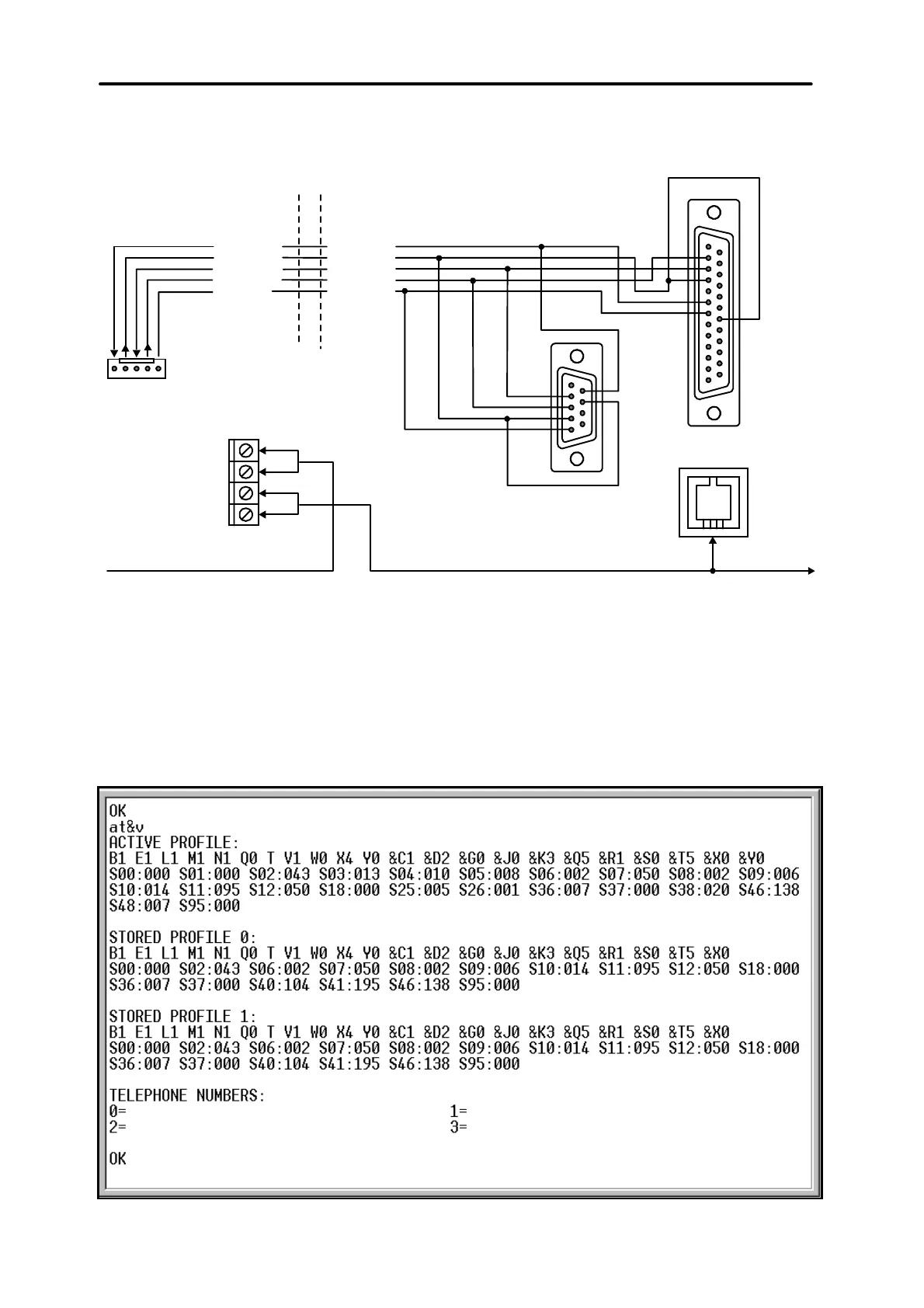
the parameter block stored as “profile 0” („STORED PROFILE 0” in Figure 26) it
must be specified E1 Q0 V1 X4 &D2 &S0 and S00:000.
DSR cont.p.
RTS cont.p.
RXD cont.p.
TXD cont.p.
COM
DSR modem
RTS modem
RXD modem
TXD modem
GND
"LINE" CONNECTOR
IN MODEM
SERIAL PORT
RS-232
TELEPHONE
CONNECTOR
IN CONTROL PANEL
TELEPHONE
TELEPHONE LINE
2
3
4
5
7
6
2
3
4
6
7
20
R-1
T-1
TIP
RING
(view of connector
at the control panel
board)
Fig. 25. Connection of an external modem to the control panel serial port.
3) If the parameters mentioned above are set correctly, the modem is ready for
operation with the control panel. If any parameter is set to other value, set it
properly. Command for parameter setting consists of fixed prefix AT and
parameter value required (for example, when profile specifies E0 V0, the
command for setting the proper parameter value is ate1v1©, after which the
modem answers OK).
Fig. 26. Correct setting of external modem parameters.