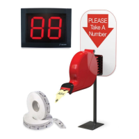
PARTS LIST
OPERATION & INSTALLATION
DISPLAY
MOUNTING
1. Identify a suitable position for the indicator assuring
the display is easily seen by the customers
2. Measure and mark the mounting holes on the wall
using the display wall mount bracket as a template
(Figure 6)
3. Drill holes using a 5/16” drill bit
4. Use the wall anchors if mounting the indicator to a
surface other than solid wood wall
5. Position the display wall mount bracket over the
drilled holes and secure with two large Phillips screws
(Figure 7)
Figure 6 Figure 7
AC POWER SUPPLY CONT
2. Choose the appropriate country outlet adapter
and slide it into the AC power supply (Figure 9)
www.satoamerica.com
AC POWER SUPPLY
1. Plug the AC Power supply into either if the two power
receptacles located on the back of the display
(Figure 8)
Figure 4
Figure 9
Figure 10
3. If required, attach the 10 ft. power extension
cable (Figure 10)
4. Plug the AC power supply into the nearest outlet
WIRELESS RECEIVER
1. Attach the pin connector of the wireless
receiver to the pins located on the back of
display (Figure 11)
2. Remove backing from adhesive strips on
the wireless receiver and mount it on the
back of the display
Figure 11

 Loading...