EasyManua.ls Logo

Saturn KDB - 161 GOM User Manual

Saturn KDB - 161 GOM
106 pages
To Next Page IconTo Next Page
Page #1 background imageLoading...
Page #1 background image
KDB-GOM
Series
- 1 -
1. Specifications of the KDB-GOM series
1.1 Kyungdong Boiler Product Features and Functions
1.2 Specifications
2. Operating Types/Constructions/Schematic Diagram
2.1 Operating Types
2.2 Constructions of the Boiler
2.3 Schematic Diagram of Operating
3. Equipment Protection and Personal Safety
4. Specifications and Functions of the Major Components
4.1 Main Heat Exchanger
4.2 Fan Assembly
4.3 Circulation Pump
4.4 Modulating Gas Control Valve
4.5 3-Way Valve
4.6 Expansion Tank
4.7 Air Pressure Switch
4.8 Hot Water Flow Sensor
4.9 High Limit Sensor(Bimetal Type)
4.10 High Limit Fuse(Fuse Type)
4.11 Heating Temperature Sensor
4.12 Ignition Transformer
4.13 Power Transformer
4.14 Domestic Hot Water Heat Exchanger
4.15 Burner Assembly
4.16 Nozzle Holder Assembly
4.17 Wiring Diagram
4.18 Main Controller
I.
Technical Information

Table of Contents

Question and Answer IconNeed help?

Do you have a question about the Saturn KDB - 161 GOM and is the answer not in the manual?

Saturn KDB - 161 GOM Specifications

General IconGeneral
BrandSaturn
ModelKDB - 161 GOM
CategoryBoiler
LanguageEnglish

Summary

I. Technical Information

1. Specifications of the KDB-GOM series

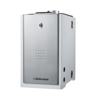
Overview of series specifications and product features.

2. Operating Types/Constructions/Schematic Diagram

Details on boiler operation, construction, and diagrams.

3. Equipment Protection and Personal Safety

Safety measures and equipment protection protocols for safe operation.

4. Specifications and Functions of the Major Components

Detailed specifications and functions of key boiler components.

4.1 Main Heat Exchanger

Technical details and specifications of the main heat exchanger.

4.2 Fan Assembly

Specifications and functions of the fan assembly.

4.3 Circulation Pump

Details on the circulation pump's type, function, and specifications.

4.17 Wiring Diagram

Electrical wiring diagrams, fault codes, and DIP switch settings.

4.18 Main Controller

Functions, settings, and operational modes of the main controller.

II. Installation of Boiler & Accessory

1. Precautions before installation

Essential precautions and guidelines before installing the boiler.

3. Installation of water piping

Guidelines for the correct installation of water piping systems.

4. Installation of the flue

Procedures for properly installing the boiler's flue system.

5. Gas piping connections

Instructions for safely connecting the gas supply lines.

6. Installation of the room thermostat

Guidance on installing and positioning the room thermostat.

III. Trial operation & Checkup

1. Checkup after installation

Steps to verify installation correctness before initial operation.

4. Trial operation

Steps for initial system startup, filling, and testing.

6. Troubleshooting

Guidance for diagnosing and resolving issues and error codes.

IV. Fuel Conversion Method

1. Conversion Kit Contents

List of components included in the fuel conversion kit.

3. Conversion Procedure

Step-by-step instructions for converting the boiler's fuel type.

V. Troubleshooting

1. Failure code #02, Low Water Level

Diagnosing and resolving issues related to low water levels.

2. Failure code #03, Ignition Failure

Troubleshooting steps for ignition failure and related components.

8. Failure code #12, Flame Failure in Combustion

Diagnosing and resolving flame failure during combustion.

11. Failure code #15, MICOM Failure

Diagnosing and resolving failures of the main controller (MICOM).

12. Failure code #16, Mechanical Overheat

Troubleshooting mechanical overheat conditions and related sensors.

VI. Procedure of disassembly/assembly

1. Room Thermostat, FR-5

Steps for disassembling and assembling the FR-5 room thermostat.

15. Domestic Water Heat Exchanger

Steps for disassembling and assembling the domestic water heat exchanger.

16. Main Heat Exchanger

Procedures for removing and installing the main heat exchanger.

VII. Part List

1. Exploded Views

Visual diagrams showing the exploded views of boiler components.

2. Part List of each Sections

Detailed lists of parts categorized by section.

Related product manuals