Step Step 25
å
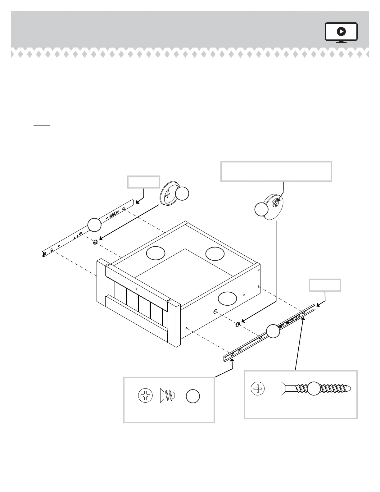
Insert a SLIDE CAM (10A) into the SMALL DRAWER SIDES (D24 and D25).
å
Fasten two NARROW EXTENSION SLIDES (BB) to the SMALL DRAWER SIDES (D24 and D25).
Use two BLACK 1-9/16" FLAT HEAD SCREWS (30S) throuh holes #1, throuh the SMALL
DRAWER SIDES, and into the SMALL DRAWER BACK (D109). Use two GOLD 5/16" FLAT
HEAD SCREWS (3S) throuh hole #3.
å
NOTE: The screw head in the CAM must be visible throuh the slotted hole in the SLIDE.
å
Repeat this step for the other SMALL drawers.
D24
D25
Open end
Open end
1
2
3
1
2
3
BB
BB
Screw head - turn CAM to line up holes in
the SLIDES with holes in DRAWER SIDES
10A
10A
D109
GOLD 5/16" FLAT HEAD SCREW
(8 used in this step)
3S
(2 screws per drawer)
BLACK 1-9/16" FLAT HEAD SCREW
(8 used in this step)
30S
(2 screws per drawer)
419954www.sauder.com/services
Pae 29