å
Fasten the UPRIGHT (C) to the SHELF (E). Tighten two
HIDDEN CAMS.
å
Fasten the BOTTOM (F) to the LEFT END (B). Tighten two
HIDDEN CAMS.
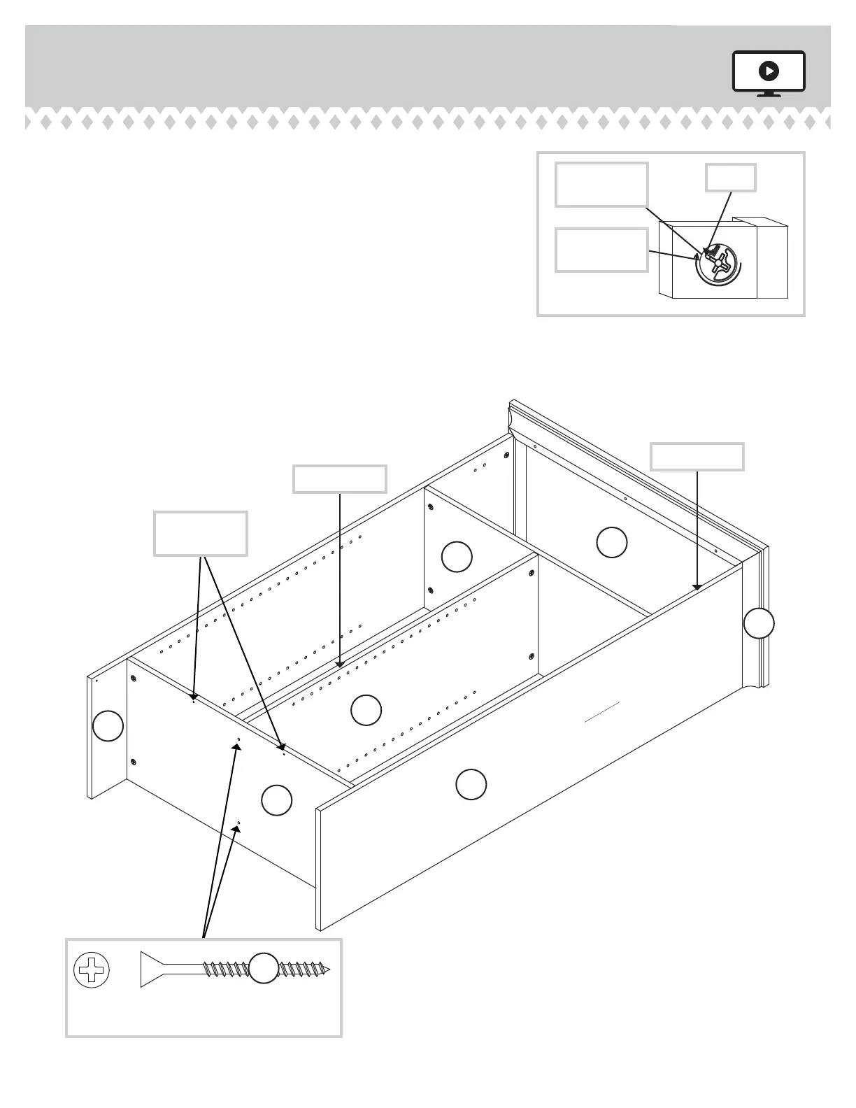
å
Fasten the BOTTOM (F) to the UPRIGHT (C). Use two
BLACK 1-7/8" FLAT HEAD SCREWS (Z).
å
Fasten the RIGHT END (A) to the SHELF (E), BOTTOM (F),
and RIGHT MOLDING (M). Tighten six HIDDEN CAMS.
Step 5
400742www.sauder.com/services
Page 9
Arrow
Minimum
190 degrees
Maximum
210 degrees
BLACK 1-7/8" FLAT HEAD SCREW
(2 used in this step)
Z
Surface
with
HIDDEN
CAMS
E
D
M
A
F
C
Surface with
HIDDEN CAMS
Surface without
HIDDEN CAMS
Finished edge
These holes
must be here.
Finished edge
B
 Loading...