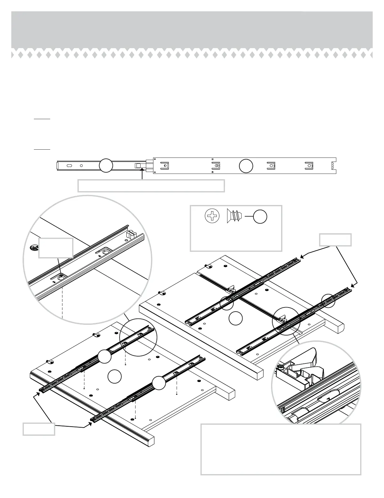
Step 9
å
Separate the EXTENSION SLIDES (R) from the EXTENSION RAILS (Q) as shown in the enlared diaram below. Be
prepared, the parts are reasy.
å
Fasten the EXTENSION RAILS (Q) to the ENDS (A and B). Use eiht GOLD 5/16" FLAT HEAD SCREWS (3S) throuh
holes #1 and #3.
å
NOTE: For each EXTENSION RAIL, turn a SCREW into the hole shown in the enlared diaram. Then, slide the inner
cartride of the EXTENSION RAIL out to fi nd the other hole that lines up with the hole in the END. Turn a SCREW into this
hole.
å
NOTE: The EXTENSION SLIDES will be used later for the DRAWERS.
Open end
Open end
GOLD 5/16" FLAT HEAD SCREW
(8 used in this step)
3S
Push the black lever in and pull the SLIDE from the RAIL.
Use this
hole.
R
Q
Q
Q
Q
Q
4
4
4
4
1
1
1
1
2
2
2
2
3
3
3
3
420040www.sauder.com/services
Pae 13
After fastening the EXTENSION RAILS to the
RIGHT END (A), the SAFETY STOPS should touch
the top edge of the RAILS. If the gap is larger than
1/16", the drawers could lock up and not open. If
this happens, open two drawers at the same time to
override the interlock system. Remove the drawers
to re-adjust the INTERLOCK TRACK assembly.
A
B