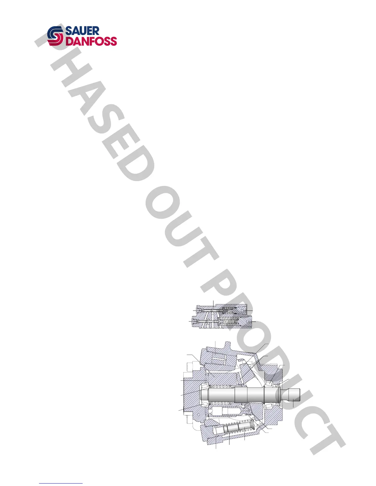
Sauer-Danfoss Series 45 G Frame open circuit piston pumps convert input torque into
hydraulic power. Rotational force is transmitted through the input shaft to the cylinder
block. The input shaft is supported by tapered roller bearings at the front and rear of
the pump and is splined into the cylinder block . A lip-seal at the front end of the pump
prevents leakage where the shaft exits the pump housing. The spinning cylinder block
contains nine reciprocating pistons. Each piston has a brass slipper connected at one end
by a ball joint. The slippers are held to the swashplate by the spring retainer and block
spring. The block spring also holds the cylinder block to the valve plate. The reciprocating
movement of the pistons occurs as the slippers slide against the inclined swashplate
during rotation. One half of the cylinder block is connected to pump inlet and the other
half to pump outlet, via the valve plate. As each piston cycles in and out of its bore, uid
is drawn from the inlet and displaced to the outlet thereby imparting power into the
system circuit. A small amount of uid is allowed to “leak” from the cylinder block / valve
plate and slipper / swashplate interfaces for lubrication and cooling. Case drain ports are
provided to return this uid to the reservoir.
The volume of uid displaced into the system circuit is controlled by the angle of the
swashplate. The swashplate is forced into an inclined position (into stroke) by the bias
piston and spring. The servo piston opposes the action of the bias piston and spring
forcing the swashplate out of stroke when hydraulic pressure in the control circuit rises
above the spring force.
The pump control, by varying the pressure at the servo piston, controls the displacement
of uid in the system circuit. Controls designed for Pressure Compensation (PC) or
Load Sensing (LS) are available. For a detailed description of control operation, refer to
Control options, operation, page 13.
GENERAL DESCRIPTION
Pump and control sectional view
 Loading...