Introduction
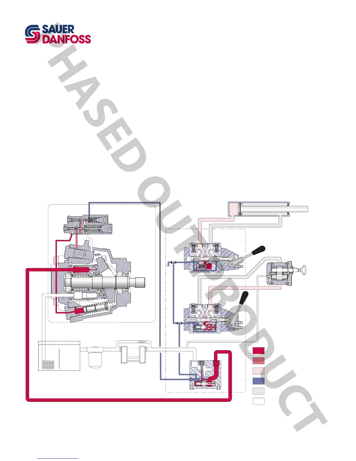
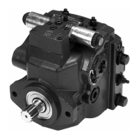
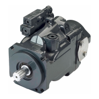
The pump receives uid directly from the reservoir through the inlet line. A screen
placed in the inlet protects the pump from large contaminants. The output of the pump
is directed to a PVG-32 multi-section load sensing directional control valve which directs
uid to the actuators in the system. Fluid returning from the system is cooled by a heat
exchanger and cleaned by a lter before returning to the reservoir.
The speed of the actuators in the system depends on the volume of uid being provided
by the pump. The operating pressure varies depending on actuator load, but is limited to
an adjustable maximum setting by the PC section of the pump control and by a system
relief valve integrated into the side module of the PVG valve.
The position of the PVG valve sets the demand for ow in the system and communicates
this to the pump control by means of a hydraulic signal (load sense signal). The pump will
provide as much ow to the system as it demands
1
while limiting the maximum pressure.
Therefore ow and pressure in the system are compensated to meet requirements.
1
Full available ow is a function of pump displacement, operating speed, and efciency. Refer to Series 45 Axial
Piston Open Circuit Pumps Technical Information, 520L0519 for details.
SYSTEM CIRCUIT
Pictorial circuit diagram


 To Next Page