The provided document is a technical information manual for the Sauer-Danfoss Series 40 Axial Piston Pumps. It details the pump's function, technical specifications, usage features, and maintenance considerations.
Function Description
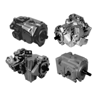
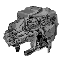
The Series 40 is a family of hydrostatic pumps designed for medium power applications, capable of handling maximum loads of 345 bar [5000 psi]. These pumps are compact, high power density units that utilize a parallel axial piston/slipper concept with a tiltable swashplate to vary displacement. Reversing the swashplate angle reverses the fluid flow from the pump, thereby reversing the direction of motor output rotation. The Series 40 family includes four frame sizes: M25, M35, M44, and M46, available in both variable displacement and tandem pump configurations.
M35, M44, and M46 pumps can incorporate an integral charge pump to supply system replenishing, cooling fluid flow, and servo control fluid flow (on M46 pumps). M25 pumps, however, require charge flow from an auxiliary circuit or a gear pump mounted on an auxiliary mounting pad. These pumps are equipped with various auxiliary mounting pads to accommodate additional hydraulic pumps for complementary hydraulic systems.
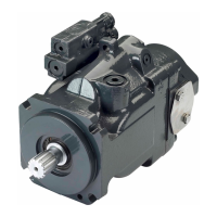
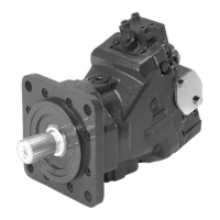
The M46 pumps offer proportional controls with manual, hydraulic, or electronic actuation, including a three-position electric control option. M25, M35, and M44 pumps feature a trunnion-style direct displacement control.
Important Technical Specifications
The Series 40 pumps are in-line, axial piston, variable, positive displacement pumps. They are available in both clockwise (CW) and counterclockwise (CCW) rotation. Installation position is discretionary, but the housing must be filled with hydraulic fluid. Filtration configurations include suction or charge pressure filtration. Other system requirements include an independent braking system, a suitable reservoir, and a heat exchanger.
Displacement and Weight:
- M25 PV: 24.6 cm³/rev [1.50 in³/rev], 19 kg [41.5 lb]
- M35 PV: 35.0 cm³/rev [2.14 in³/rev], 25 kg [55 lb]
- M44 PV: 43.5 cm³/rev [2.65 in³/rev], 25 kg [55 lb]
- M46 PV: 46.0 cm³/rev [2.81 in³/rev], 33 kg [73 lb]
- M25 PT: 24.6 x 2 cm³/rev [1.50 x 2 in³/rev], 24 kg [56 lb]
- M35 PT: 35.0 x 2 cm³/rev [2.14 x 2 in³/rev], 45 kg [99 lb]
- M44 PT: 43.5 x 2 cm³/rev [2.65 x 2 in³/rev], 45 kg [99 lb]
- M46 PT: 46.0 x 2 cm³/rev [2.81 x 2 in³/rev], 59 kg [131 lb]
Operating Parameters:
- Case Pressure: Continuous 1.7 bar [25 psi], Maximum 5.2 bar [75 psi].
- Speed Limits (Rated @ max angle): M25 PV/PT 4000 rpm, M35 PV/PT 3600 rpm, M44 PV/PT 3300 rpm, M46 PV/PT 4000 rpm.
- Speed Limits (Maximum @ max angle): M25 PV/PT 5000 rpm, M35 PV/PT 4500 rpm, M44 PV/PT 4100 rpm, M46 PV/PT 4100 rpm.
- Speed Limits (Minimum): All models 500 rpm.
- System Pressure: Continuous 210 bar [3000 psi], Maximum 345 bar [5000 psi].
- Theoretical Max Flow (at rated speed per pump): M25 PV/PT 100 l/min [26.0 US gal/min], M35 PV/PT 126 l/min [33.4 US gal/min], M44 PV/PT 145 l/min [38.3 US gal/min], M46 PV/PT 184 l/min [48.6 US gal/min].
- Inlet Pressure: Continuous 0.8 bar absolute [6.3 in Hg vacuum], Maximum 0.7 bar absolute [9.2 in Hg vacuum].
Fluid Specifications:
- Viscosity: Minimum 7 mm²/sec (cSt) [47 SUS], Continuous 12-60 mm²/sec (cSt) [70-278 SUS], Maximum 1600 mm²/sec (cSt) [7500 SUS].
- Temperature: Minimum -40°C [-40°F], Continuous 82.2°C [180°F], Maximum 104.4°C [220°F].
- Cleanliness: ISO 4406 Class 18/13 or better.
- Filtration Efficiency: Suction filtration β₁₀≥1.5, Charge filtration β₁₀≥10.
Shaft Options:
Series 40 pumps are available with splined, straight keyed, and tapered shaft ends. Torque ratings assume no external radial loading. Continuous torque ratings for splined shafts are based on splined tooth wear, assuming a mating spline with minimum hardness of Rc 55 and full spline depth with good lubrication. Maximum torque ratings are based on shaft torsional strength and a maximum of 200,000 load reversals.
Usage Features
- Integral Charge Pump: M35, M44, and M46 pumps can be equipped with integral charge pumps for replenishing, cooling, and servo control. M25 pumps require an external charge supply.
- Charge Relief Valve: An integral charge pressure relief valve sets charge pressure, porting flow to case. It is factory set at 1800 min⁻¹ (rpm) in neutral. Field adjustment with shims is possible.
- Check/High Pressure Relief Valve: These valves maintain circuit pressure, allowing charge flow to replenish the low-pressure side of the working loop and providing overpressure protection to the high-pressure side. Available in various settings, or as check-only valves.
- Displacement Limiters (M46 PV/PT): Optional mechanical displacement limiters in the servo piston allow limiting maximum displacement in either direction. An externally adjustable limiter screw is available on one side.
- Auxiliary Mounting Pads: All Series 40 pumps feature auxiliary mounting pads for additional hydraulic pumps.
- Control Options:
- Direct Displacement Control (DDC) (M25, M35/44 PV/PT): Provides simple, positive control by proportionally moving the swashplate based on control shaft movement. No internal neutral return mechanism; requires external linkage for neutral return.
- Manual Displacement Control (MDC) (M46 PV/PT): Converts a mechanical input signal to a hydraulic signal via a spring-centered 4-way servo valve, porting hydraulic pressure to a double-acting servo piston. This high-gain control offers low input forces, maintains pump output regardless of load, and returns to neutral upon prime mover shutdown or loss of charge pressure.
- Hydraulic Displacement Control (HDC) (M46 PV/PT): A two-stage design using a hydraulic input signal to operate a spring-centered 4-way servo valve. Provides output flow proportional to the hydraulic command signal, allowing remote control. Returns to neutral without a command signal or upon loss of charge pressure.
- Electrical Displacement Control (EDC) (M46 PV/PT): A three-stage control similar to HDC, but uses an electrohydraulic Pressure Control Pilot (PCP) valve. Converts an electrical input signal (current) to a hydraulic signal for proportional output flow. Suited for remote or automatic control and returns to neutral without an electrical command signal or upon loss of charge pressure.
- Three-Position Electrical Control (FNR) (M46 PV/PT): A two-stage control using a solenoid-operated 3-position, 4-way valve to move pump displacement to maximum in either direction. Provides electric control, returns to neutral if voltage is lost, and is ideal for applications not requiring proportional control.
Maintenance Features
- Filtration: Proper filtration is crucial to prevent damage and premature wear. Series 40 pumps require fluid cleanliness at ISO 4406-1999 class 22/18/13 or better. Filters can be located on the inlet (suction filtration) or discharge (charge pressure filtration) side of the charge pump.
- Filter Bypass Valve: Necessary in charge pressure filtration circuits to prevent filter damage and fluid bypass during high pressure drop or cold start-up conditions. A visual or electrical bypass indicator is recommended for proper filter maintenance.
- Fluid Temperature and Viscosity: Maintain fluid temperature and viscosity within specified limits to ensure maximum efficiency and bearing life. Maximum temperature is based on material properties and should be measured at the hottest point in the system, usually the case drain.
- Charge Pressure: Maintain a minimum of 6 bar [87 psi] above case pressure in the low side of the system loop for proper lubrication and rotating group operation.
- Case Pressure: Maintain case pressure within specified limits and ensure the housing is filled with hydraulic fluid.
- Displacement Limiter Adjustment (M46 PV/PT): When adjusting displacement limiters, retorque the sealing lock nut to prevent unexpected changes in output and external leakage.
- Reservoir Design: The reservoir should provide clean fluid, dissipate heat, and remove entrained air. Its capacity depends on fluid volume changes and charge pump flow. Locate the suction line near the bottom with a 100-125 µm screen, and return lines below the lowest fluid level, far from the outlet. Use baffles to promote de-aeration and reduce surging.
- Case Drain Usage for Tandem Pumps: For adequate case flushing on tandem pumps, it is recommended to use the rear housing drain ports as the case drain.
- Bearing Life: While normal bearing life typically exceeds hydraulic unit life in vehicle propulsion drives, a bearing life review is recommended for non-propel drives with constant operating speeds and pressures. Optional high-capacity bearings are available if continuously applied external radial loads exceed 25% of the maximum allowable.
- Shaft Loading: Tapered output shafts or clamp-type couplings are recommended for applications with radial shaft side loads. Auxiliary mounting pads may require additional structural support if subject to severe vibratory or high G loading.