520L0635 • Rev EH • June 2009
64
Series 40 Axial Piston Pumps
Technical Information
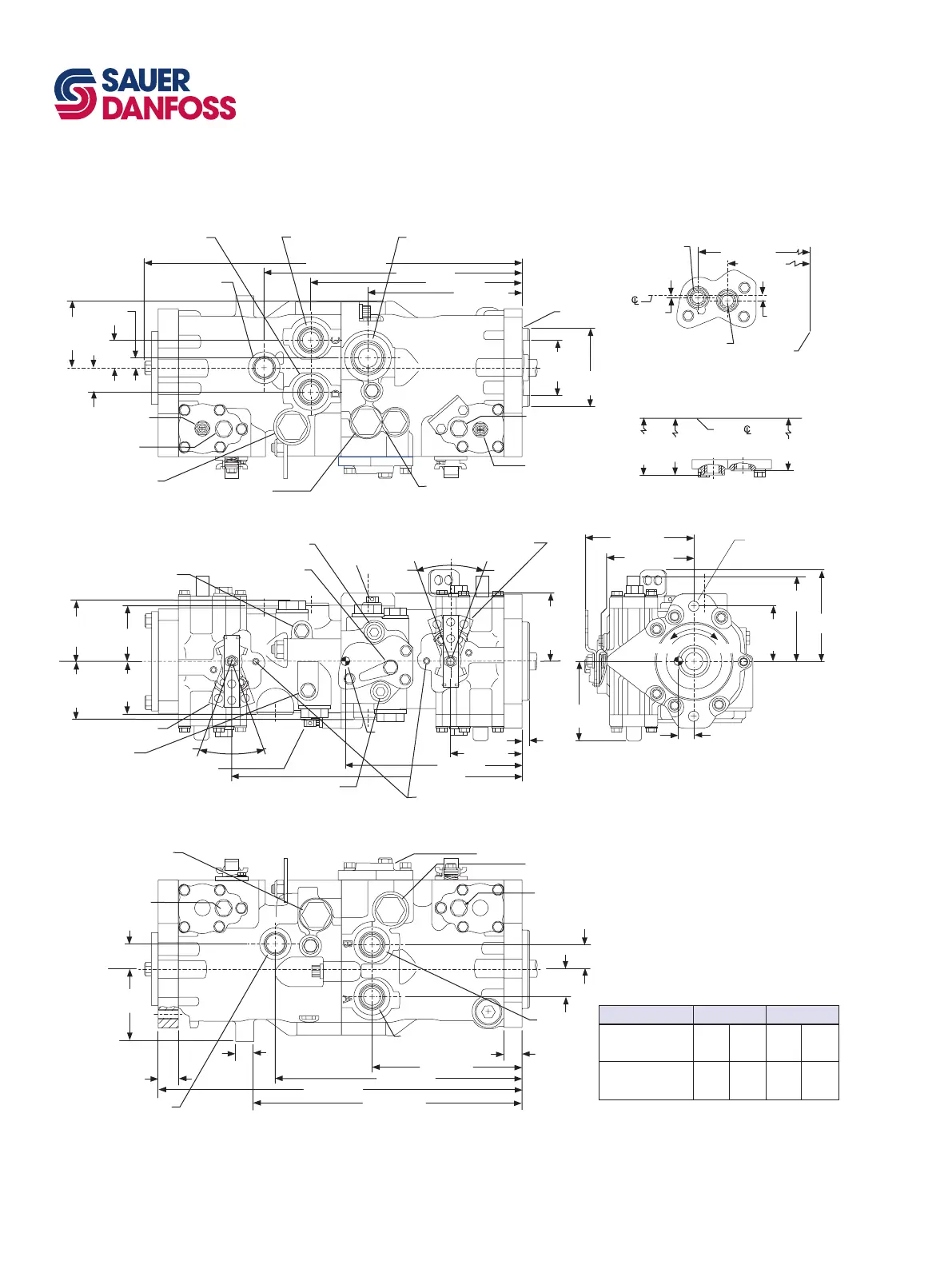
Installation drawings
*All ports are SAE straight thread o-ring ports per SAE J514, unless otherwise specied.
Shaft rotation is determined by viewing pump from input shaft end.
Contact your SAUER-DANFOSS representative for specic installation drawings.
Dimensions in mm [in]
3.14 [79.8]
system
port A & B
73.2 [2.88]
case drain
89.9 [3.54]
Charge
pump
inlet
9/16 - 18*
charge pressure
gauge port M3
Front view (with MDC)
233.7 [9.2]
377.4 [14.86]
92.7 [3.65]
9/16 - 18* system pressure
gauge port
M1 front (port A)
**Bypass
valve
(front)
20°20°
Top view (with MDC, charge pump, and suction filtration)
Bottom view (with MDC and suction filtration)
Manual displacement control
handle position up
Remote filtration
or no charge pump
171.7 [6.76]
mounting
flange
(ref.)
7/8 - 14*
to remote filter D
(pressure filter
option)
7/8 - 14*
from remote filter E
(pressure filter option)
or charge pressure inlet E
(no charge pump option)
212.3 [8.36]
7.1
[0.28]
2.3
[0.09]
Pump
73.03
[2.875]
(2) places
14.27 dia.
[0.562]
(2) places
126.2 max.
[4.97]
116.3
[4.58]
141.7 [5.58]
for MDC
9.65
[0.38]
Disp.limiter #2
(option)
203.7 [8.02]
1-1/16 - 12*
case outlet L1
274.8 [10.82]
341.4 [13.44]
493.0 [19.41] max
1-5/8 - 12*
charge pump inlet S
Check/relief valve
(for Port D)
Charge pressure relief valve
Check/relief valve
(for port A)
101.6 dia.
[4.00]
72.6
min dia.
[2.86]
Disp.limiter #3
(option)
9/16 - 18*
servo pressure
gauge port M5 rear
39.6
[1.56]
30.0
[1.18]
13.2
[0.52]
91.2
[3.59]
max
70.6 [2.78]
case drain
(alt.)
79.8 [3.14]
system
port C & D
1-1/16 - 12*
Case outlet (alt.) L2
26.9 [1.06]
1-5/16 - 12*
port D
1-5/16 - 12*
port C
9/16 - 18*
servo pressure
gauge port M4 front
9/16-18* system pressure
gauge port M2 rear
(for port D)
9/16 - 18*
system pressure
gauge port
M1 rear
(for port C)
9/16 - 18*
servo pressure
gauge port M4 rear
9/16 - 18*
servo pressure
gauge port M5 front
22.6 [0.89]
195.6 [7.70]
39.6
[1.56]
30.0
[1.18]
1-5/16 - 12*
port A
1-5/16 - 12*
port B
326.6 [12.86]
Check /relief valve
(for port B)
474.5 [18.68]
33.5
[1.32]
Suction filtration adapter
Approx.
center
of gravity
9/16 - 18* system pressure
gauge port M2 front (for port "B")
Control pressure gauge ports
1/8-27 NPTF (MDC only)
Left side view (with MDC,
charge pump, and suction filtration)
Bypass valve
rear
20°
20°
CWCCW
20.4 [0.8]
MDC handle
position Down
Check/relief valve
(for port C)
118.9 max.
[4.68]
108.2 max.
[4.26]
0.8 R max.
[0.03]
LEFT SIDE VIEW
Pump
131.9
[5.19]
134.4
[5.29]
145.3
[5.72]
(no CP)
P100 620E
25
[0.984]
91.7 [3.61]
336.6 [13.25]


 To Next Page