63
520L0635 • Rev EH • June 2009
Series 40 Axial Piston Pumps
Technical Information
Installation drawings
Dimensions in mm [in]
*All ports are SAE straight thread o-ring ports per SAE J514, unless otherwise specied.
Shaft rotation is determined by viewing pump from input shaft end.
Contact your SAUER-DANFOSS representative for specic installation drawings.
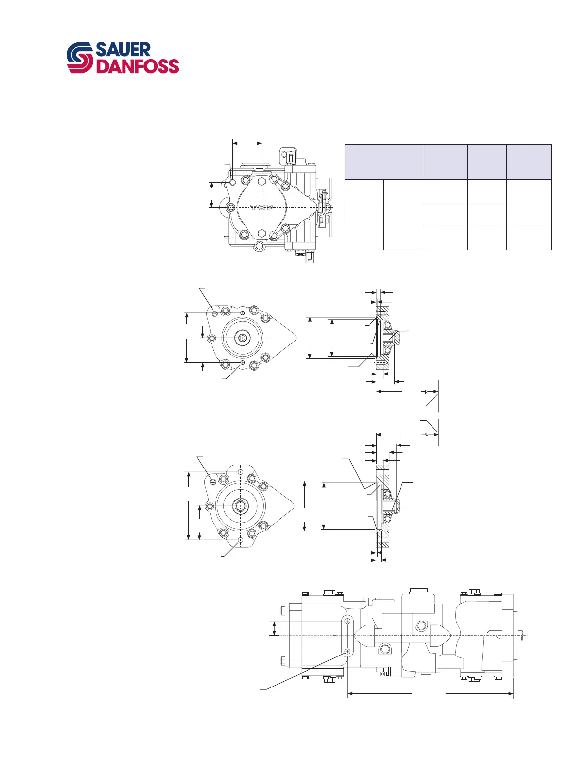
M46 TANDEM PUMP
DIMENSIONS
0.375-16 Thd.
18.3 [0.72] min.
full thd. depth
(2) holes
SAE B Auxiliary mounting flange
Option B
O-ring seal required
ref. 94.97 [3.739] ID x
1.78 [0.070] dia. cross section
SAE A Auxiliary mounting flange
options A and D
53.19
[2.094]
106.38
[4.188]
P pitch dia
30° pressure angle
N teeth,16/32 pitch
fillet root side fit
class no.1 1963 SAE
(see table)
82.6 dia.
[3.252]
88.65 dia.
[3.490]
474.5
[18.68]
Mounting flange
(ref.)
10.7 [0.42] min.
P pitch di
a.
30° pressure angle
N teeth,16/32 pitch
fillet root side fit
per ANSI B92.1-1970
(See Table)
474.5
[18.68]
Y min.
101.65 di.
[4.002]
1.0 max. R
[0.04]
1.0 max. R
[0.04]
105.92
[4.170]
Mounting flange
(ref.)
26.9 [1.06] (ref.)
Rear mounting hole
(ref.)
8.6 [0.34] min.
1.0 max. R
[0.04]
0.5 max. R
[0.02]
O-ring seal required
ref. 82.22 [3.237] ID x
2.62 [0.103] dia. cross sec tion
Y min.
14.7 [0.58] min
1.96 [0.077]
1.35 [0.053]
14.7 [0.58] min.
14.27 [0.562] dia.
thru (2) holes
73.03
[2.875]
146.05
[5.75]
Rear mounting hole
(ref.)
Rear view
no auxiliary mounting flange
0.500-13 Thd. thru
rear mounting
hole
59.7
[2.35]
51.3
[2.02]
P100 628E
Auxiliary mounting flange
Auxiliary
mounting
flange
Spline
pitch dia.
P
Number
of teeth
N
Minimum
clearance
Y
SAE A Option A
14.30
[0.563]
9
35.6
[1.40]
SAE A Option D
17.46
[0.688]
11
38.1
[1.50]
SAE B Option B
20.72
[0.813]
13
47.5
[1.87]
Rear mounting boss
M12 x 1.75
6H Thd. X2
P104 425E
32.51 [1.28]
X2
349 [13.74]
M46 PV adjustable displacement limiter (option)
M46 PT auxiliary mounting flange and coupling options


 To Next Page