65
520L0635 • Rev EH • June 2009
Series 40 Axial Piston Pumps
Technical Information
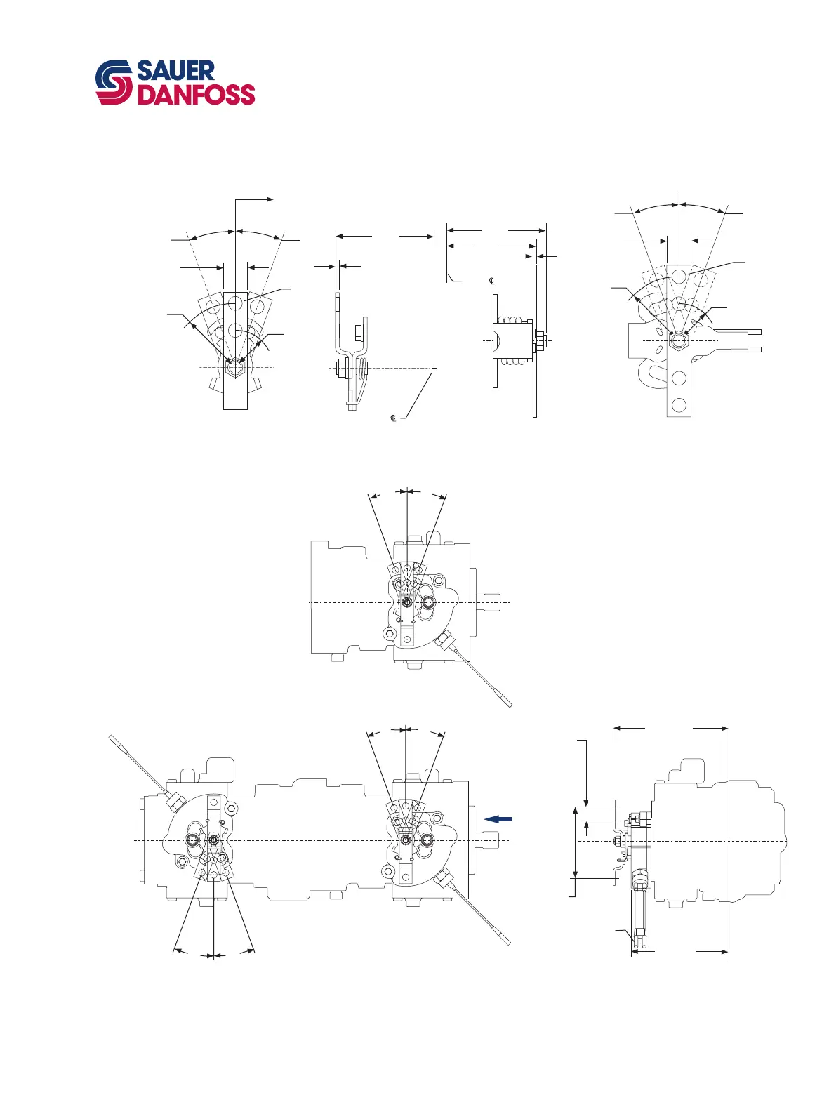
Installation drawings
Dimensions in mm [in]
*All ports are SAE straight thread o-ring ports per SAE J514, unless otherwise specied.
Shaft rotation is determined by viewing pump from input shaft end.
Contact your SAUER-DANFOSS representative for specic installation drawings.
M46 CONTROL MODULE
DIMENSIONS
M46 PV/PT manual displacement control handle
19.05 [0.75]
10.08
[0.397]
dia. (2)
20°
50.8
[2.00]
R
29.5
[1.16]
R
20°
Mounting
flange location
(ref .)
141. 5
[5.57]
3.18
[0.125]
Pu mp
19.05 [0.75]
Ø10.08
[0.397]
20°
50.8 [2.00] R
29.5 [1.16] R
20°
132.3
[6.39]
152.8
[6.01]
4.75
[0.187]
Pu mp
With heavy spring
P100 629E
M46 PV/PT manual displacement control with neutral start switch
Side view
Variable pump with MDC and NSS
"X"
20°
20°
20°
20°
145. 1
[5.71]
105. 9
[4.17]
(2) places
Switch with weather pack
tw o-w ay connec to r
171. 7
[6.76]
21.34
[0.84]
(2) places
20°
20°
Side view tandem pump with MDC and NSS
P100 630E
View X front view
Variable pump with MDC and NSS


 To Next Page