520L0635 • Rev EH • June 2009
22
Series 40 Axial Piston Pumps
Technical Information
System design parameters
MOUNTING FLANGE
LOADS
Shock load moment is the result of an instantaneous jolt to the system. Continuous
load moments are generated by the typical vibratory movement of the application.
Avoid exces sive loading of the mounting ange such as adding tandem mounted
auxiliary pumps and/or sub jecting pumps to high shock loads. Design pump
applications to stay within the allowable shock load moment and allowable continuous
load moment.
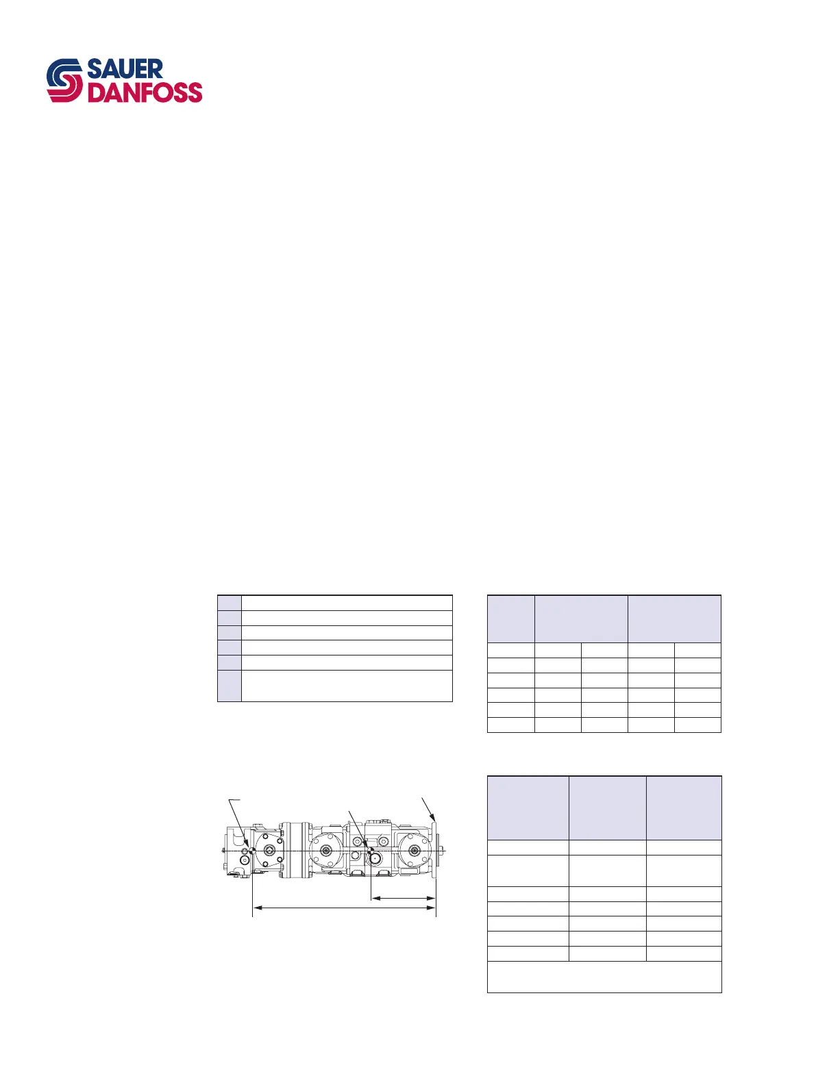
Use the following formulas to estimate overhung load moment for multiple pump
mountings:
M
S
= G
S
(W
1
L
1
+ W
2
L
2
+ ... +W
n
L
n
)
M
C
= G
C
(W
1
L
1
+ W
2
L
2
+ ... +W
n
L
n
)
Refer to Installation drawings, page 52, to nd pump length (L). Refer to the table
Specifications, page 10, to nd pump weight (W). An exact measure of W will depend on
the pump’s features.
The tables below show allowable overhung load moment values. If system parameters
exceed these values add additional pump support.
Estimated maximum and continuous acceleration factors for some typical Series 40
applications are shown. Applications which experience extreme resonant vibrations
may require additional pump support. Typical continuous (vibratory) values can vary
signicantly due to changes in engine and pump conguration and mounting methods.
M
s
Shock load moment
M
c
Continuous load moment
G
s
Maximum shock acceleration (Gs)
G
c
Continuous (vibratory) acceleration (Gs)
W
n
Weight of nth pump
L
n
Distance from mounting ange to center of gravity
of nth pump
Frame
size
Continuous load
moment (M
c
)
N•m [in·lbf]
Shock load moment
(M
s
)
N•m [in·lbf]
M25 PV 361 [3200] 617 [5470]
M25 PT 361 [3200] 559 [4950]
M35 PV 517 [4600] 832 [7400]
M35 PT 517 [4600] 754 [6700]
M46 PV 517 [4600] 832 [7400]
M46 PT 517 [4600] 754 [6700]
Application
Continuous
(vibratory)
acceleration
(G
c
)
Maximum
(shock)
acceleration
(G
s
)
Skid steer loader 4 10
Trencher
(rubber tires)
3 8
Asphalt paver 2 6
Windrower 2 5
Aerial lift 1.5 4
Turf care vehicle 1.5 4
Vibratory roller 6 10
* Applications which experience extreme resonant vibrations
require addition pump support.
Mounting
flange
CG
Pump 1
CG
Pump 2
L1
L2
P100 596E
Overhung loading parameters
Shaft loading parameters
Allowable overhung parameters
G-factors for sample applications


 To Next Page