EasyManua.ls Logo

Sauer Danfoss 40 Series - Installation Drawings; M25 Variable Pump Dimensions

Sauer Danfoss 40 Series
72 pages
Print Icon
To Next Page IconTo Next Page
To Previous Page IconTo Previous Page
Loading...
520L0635 • Rev EH • June 2009
52
Series 40 Axial Piston Pumps
Technical Information
Installation drawings
*All ports are SAE straight thread o-ring ports per SAE J514, unless otherwise specied.
Shaft rotation is determined by viewing pump from input shaft end.
Contact your SAUER-DANFOSS representative for specic installation drawings.
Dimensions in mm [in]
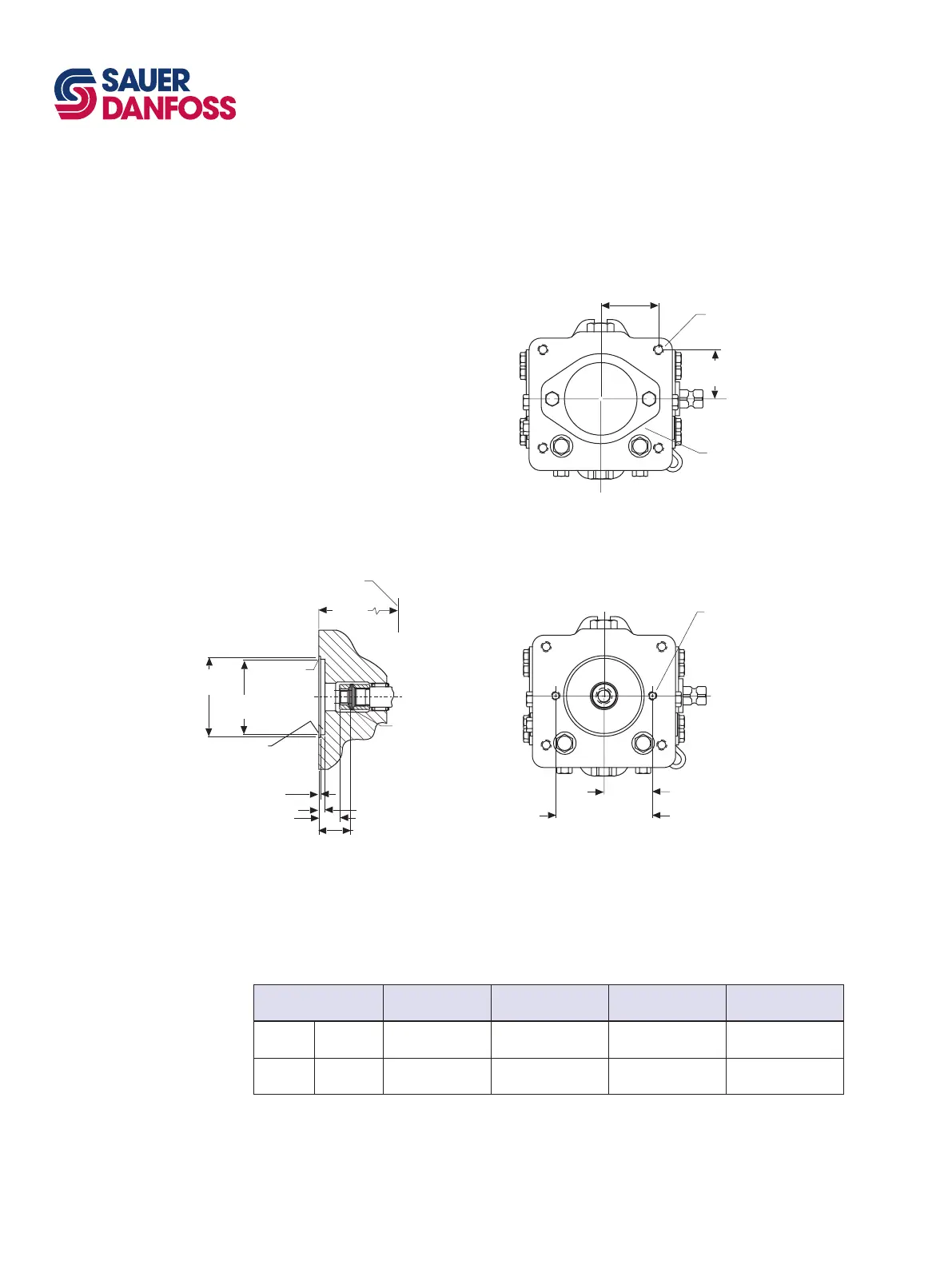
M25 VARIABLE PUMP
DIMENSIONS
Auxiliary mounting flange
0.375-16 UNC-2B thd
19.8 [0.78 min. fullt
hd.
(2) places
53.188
[2.094]
106.375 [4.188]
Running cover
SAE A Auxiliary mounting
flange
0.5 max R
[0.02]
88.65 dia
[3.490]
82.6 dia
[3.252]
1.96 [0.077]
6.1 [0.24] min.
M min.
Y min.
Mounting flange
[ref.
]
P Pitch diameter
30 pressure angle
N teeth, 16/32 pitch
fillet root side fit
per ANSI B92.1-1970
Class 7 (see table)
O-ring seal required
ref. 82.22 [3.237] I.D.x
2.62 [0.103] cross section
189.7
[7.47]
53.975 [2.125]
(4) places
63.50 [2.500]
(4) places
0.4375-14 UNC-2B thd.
19 [0.75] min. full thd.
(4) places
Running cover
P100 603E
Auxiliary mounting
flange
Spline pitch dia.
P
Number of teeth
N
Shaft clearance
Y
Coupling clearance
M
SAE A Option A
14.30
[0.563]
9
34.5
[1.36]
22.6
[0.89]
SAE A Option D
17.46
[0.688]
11
39.6
[1.56]
25.9
[1.02]
M25PV Auxiliary flange coupling options

Table of Contents