520L0635 • Rev EH • June 2009
46
Series 40 Axial Piston Pumps
Technical Information
Control options
Input Shaft Rotation
CW CCW
PV or front PT
Higher pressure into control port: X1 X2 X1 X2
Port A ow Out In In Out
Port B ow In Out Out In
Rear PT
Higher pressure into control port: X1 X2 X1 X2
Port C ow In Out Out In
Port D ow Out In In Out
High servo gauge port M4 M5 M4 M5
Refer to pump installation drawing for port locations.
Response time
The time required for the pump output ow to change from neutral to full ow
(acceleration) or full ow to neutral (deceleration) is a function of the size of the orices
in the servo passages.
A range of orice sizes is available to assist in matching the rate of swashplate response
to the acceleration and deceleration requirements of the application. The table below
shows some sample response times under certain conditions. (These gures assume
1775 min
-1
(rpm), 140 bar [2000 psi] system pressure, and 20 bar [290 psi] charge
pressure.) Test system response to determine the proper orice selection for the desired
response.
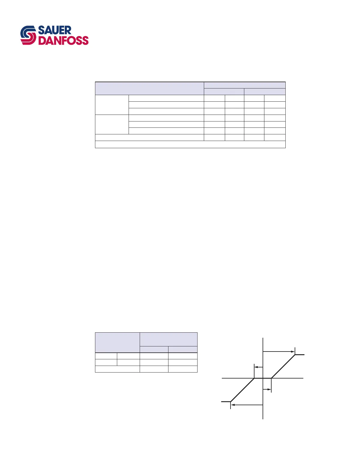
Control input signal requirements
The standard command signal range required to stroke the pump between neutral and
full stroke is 1.3 to 11.7 bar [19 to 170 psi] differential. The maximum command pres sure
must not exceed 27.5 bar [400 psi].
HDC options
The HDC can be tailored to respond to a higher signal pressure. Optional heavy spring
packs are available that operate in the 3 to 14 bar [44 to 200 psi] range and the 5 to 15
bar [70 to 220 psi] range.
Orifice diameter*
mm [in]
Average response time
(seconds)
Acceleration Deceleration
0.9 [0.037] 1.6 1.3
1.4 [0.055] 0.9 0.7
None 0.4 0.3
*Contact Sauer-Danfoss for special orice
combinations
100%
100%
Signal pressure
Signal pressure
Pump
displacement
Pump
displacement
a
b
-a
-b
Pump displacement vs hydraulic signal
HYDRAULIC
DISPLACEMENT
CONTROL (HDC) M46
VARIABLE PUMP
(continued)
Pump flow direction with HDC control
HDC response time


 To Next Page