EasyManua.ls Logo

Sauer Danfoss 40 Series - Pump and Control

Sauer Danfoss 40 Series
72 pages
Print Icon
To Next Page IconTo Next Page
To Previous Page IconTo Previous Page
Loading...
53
520L0635 • Rev EH • June 2009
Series 40 Axial Piston Pumps
Technical Information
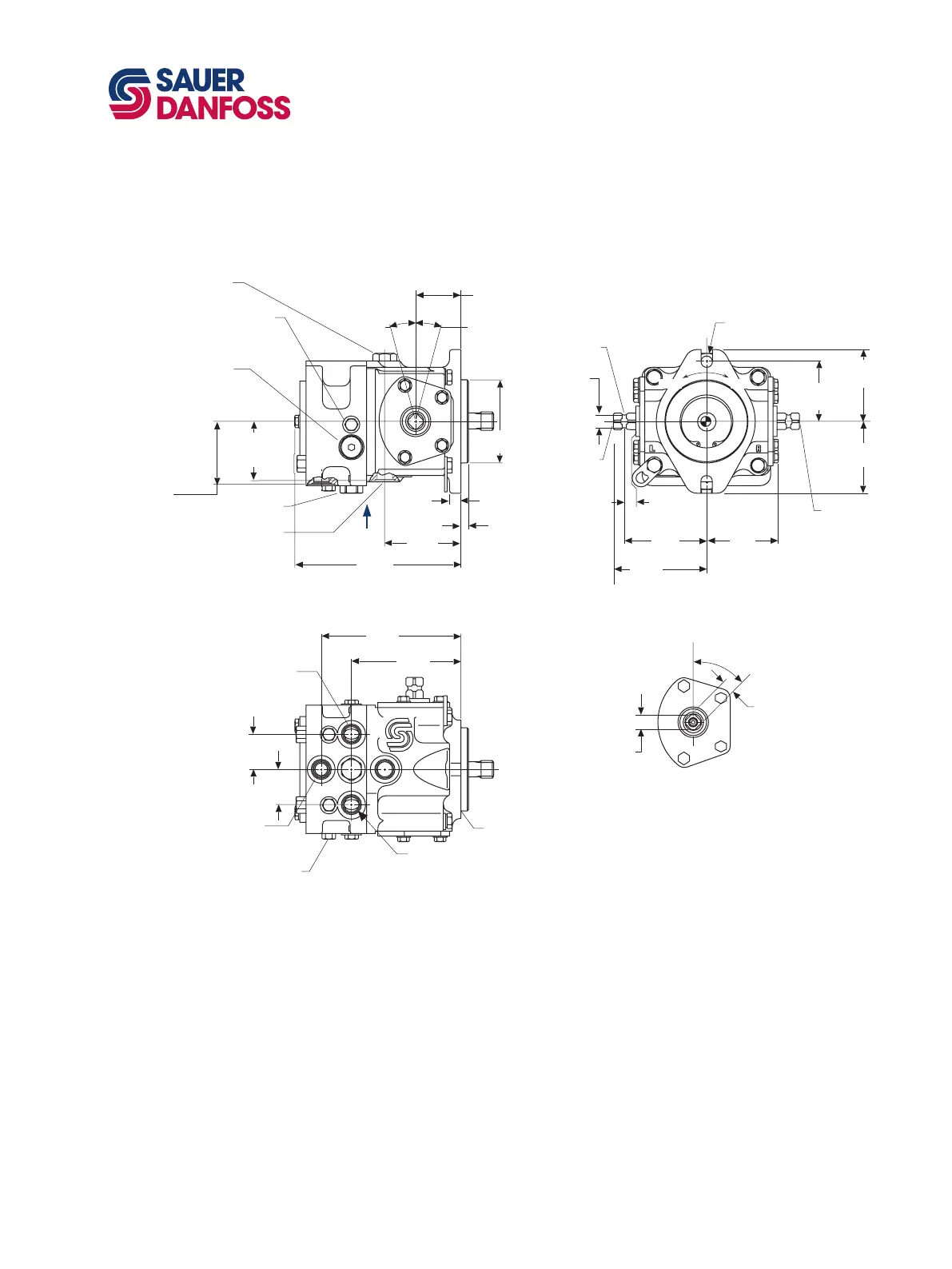
Installation drawings
Dimensions in mm [in]
*All ports are SAE straight thread o-ring ports per SAE J514, unless otherwise specied.
Shaft rotation is determined by viewing pump from input shaft end.
Contact your SAUER-DANFOSS representative for specic installation drawings.
Pump and control
12.7 [0.50]
mi n.
to shoulder
14.27 [0.562] di a.
(2) places
73.02 [2.875]
(2) places
99. 1
[3.90]
112. 3
[4.42]
87.4 [3.44]
(2) places
88. 4
[3.48]
4.57 R
[0.180]
15.24 di a.
[0.600]
Co ntro l
trunnion
le ft side
option DL
88. 4
[3.48]
both
sides
72.1 [2.84]
Case Outlets
(2) places
202. 2
[7.96]
54. 9
[2.16]
92. 7
[3.65]
13. 0
[0.51]
77. 2
[3.04]
(2) System
por ts and
(1) chg. inle
t
101.6 di a
[4.00]
7/8-14*
case outlet L1
9. 4
[0.37]
Charge pressur e
relief valv
e
15°
max. displ.
15°
max. displ.
7/16-20*
Change pressur e
gauge po rt
M3
Co ntro l
trunnion
right side
option DR
133. 6
[5.26]
170. 7
[6.72]
7/8-14*
Charge pressure inlet E
7/8-14*
Po rt
A
7/8-14*
Po rt B
7/8-14*
case outlet
(alternate) L2
19.84 di a.
[0.781]
45°
15.82 [0.623]
(2) Places
Control trunion detail
CC W
CW
Bypass/check/relief va lv e
this side f or po rt A
opposite side f or po rt B
(with 5/16 internal hex)
7/16-20*
gauge po rt
this side f or po rt A M1
opposite side f or po rt
B M2
W
43. 2
[1.70]
43. 2
[1.70]
0.8 R ma x.
[0.03]
P100 602E
M25 VARIABLE PUMP
DIMENSIONS
(continued)

Table of Contents