EasyManua.ls Logo

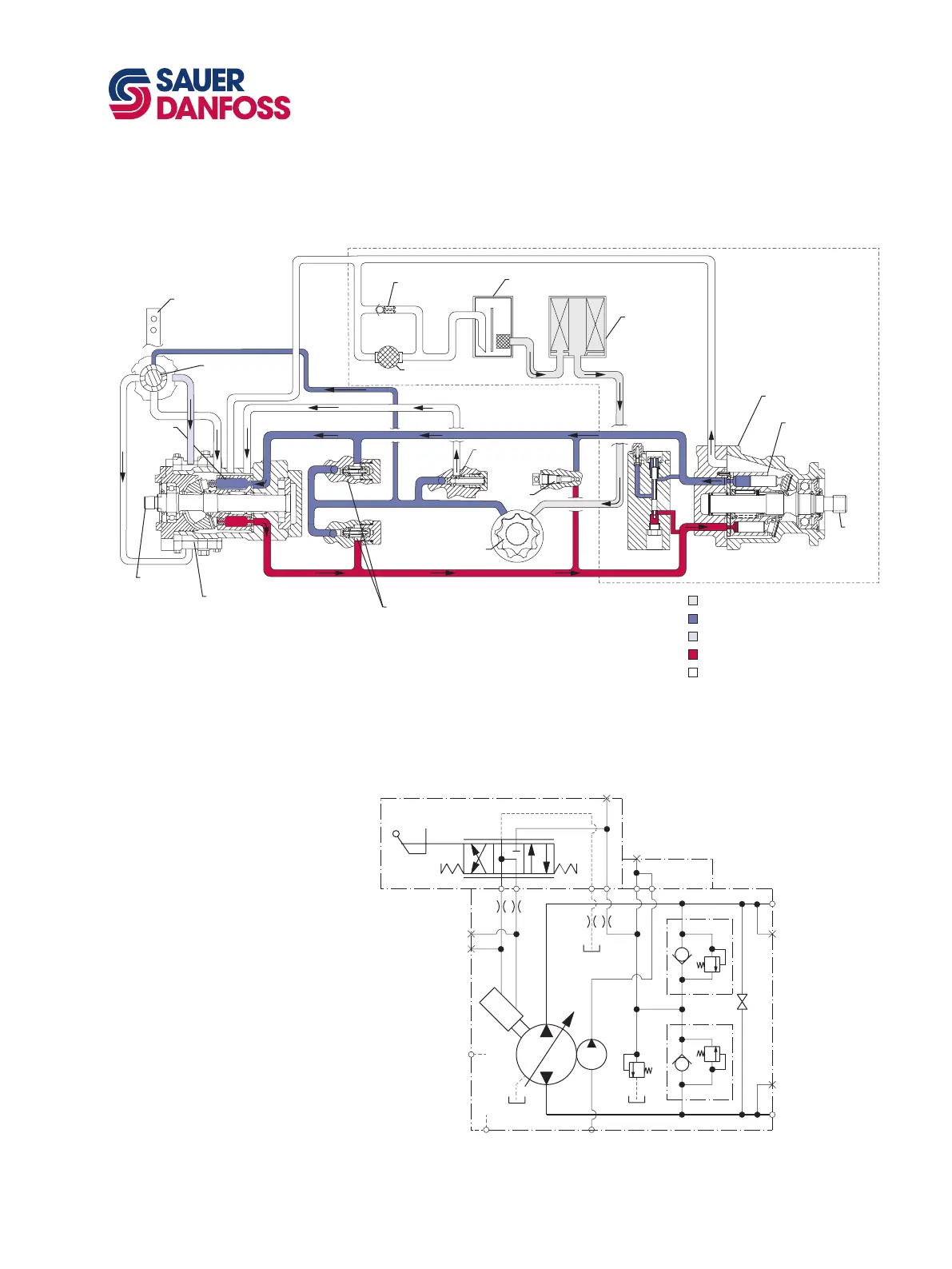
Sauer Danfoss 40 Series - System Circuit Diagram; M46 Pump Schematic Diagram

Sauer Danfoss 40 Series
72 pages
Print Icon
To Next Page IconTo Next Page
To Previous Page IconTo Previous Page
Loading...
9
520L0635 • Rev EH • June 2009
Series 40 Axial Piston Pumps
Technical Information
General description
SYSTEM CIRCUIT
DIAGRAM
Input
shaft
Suction flow
Servo pressure
High pressure
Case flow
Charge pressure
Output
shaft
Cylinder
block
assembly
Filter
Charge
pump
Reservoir
Fixed displacement
motor
Cylinder
block
assembly
Heat
exchanger
Check valves
w/ high pressure
relief valve
Variable
displacement
pump
Heat exchanger
bypass
Charge relief
valve
Displacement
control
valve
Control
handle
Bypass
valve
Loop flushing
module
P100 586E
A Series 40 - M46 variable pump is shown in a hydraulic circuit with a Series 40 - M35 xed motor. The pump shown
features manual displacement control. The circuit features suction ltration and heat exchanger.
M46 PUMP SCHEMATIC
DIAGRAM
B
M2
M1
A
E
L1
L2
M5
M4
S
M3
B N A
P100 587E

Table of Contents