51.377/1
Sauter Components
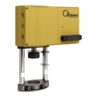
AVM 234S: Valve actuator with SUT positioner
How energy efficiency is improved
Automatic adaptation to valve, precision control and high energy efficiency with minimal operating noise.
Areas of application
For use with through or three-way valves in the V/BUD and V/BUE DN65…150 series, and V/BUG,
V/BUS, VUP and V/B6R DN15…150. For controllers with continuous output (0…10 V or 4…20 mA) or
switching output (2-point or 3-point control).
Features
• Pushing force of at least 2500 N
• Stepping motor with SUT (Sauter Universal Technology) electronic control unit and electronic
load-dependent cut-off
• Automatic detection of control signal applied (continuous or switching), indicated by two LEDs
• The type of characteristic (linear, quadratic or equal-percentage) can be set on the actuator
• Automatically adapts to valve stroke between 8 and 49 mm; captive even in the event of a
power failure
• Direction of travel can be selected via screw terminals when making electrical connection or
remotely
• Coding switches for selecting the characteristic and the running time (2, 4 or 6 s/mm)
• Lever for external manual adjustment, with motor cut-off, and for triggering a re-initialisation
• Easy assembly with valve; spindle is connected automatically when control voltage is applied
• The availability of numerous adaptors enables the actuator to be fitted to third-party valves
Technical description
• Power supply 230 V with modules or direct connection for 24 V~ or 24 V=; continuous activa-
tion also permissible at 230 V
• Two-part housing made of fire-retardant yellow plastic and seals to IP66
• Maintenance-free gearbox of sintered steel, gearbox plate of steel
• Patented actuator–valve coupling
• Mounting column made of stainless steel; mounting bracket (for fitting the valve) of cast light
alloy
• Electrical connections (max. 2.5 mm²) with screw terminals
• Three pre-scored cable inlets for M20×1.5 (2×) and M16×1.5
• Installation position: vertically upright to horizontal, but not upside down
Y07552
M
100 %
0 V Output signal y 10 V
B07650
0 %
Direction
of
o
pe
r
at
i
on
2
D
i
recti
o
n
of
op
e
ra
t
i
on
1
s/mm
mm
force
supply
1)
kg
Valve actuator for valves: VUD / BUD, VUE / BUE, VUG / BUG, VUS / BUS and VUP
AVM 234S F132
2 / 4 / 6 14…40 2500 24 V~/= 4.1
matching with assembly for valve series: V6R / B6R
AVM 234S F132-5
2 / 4 / 6 14 2500 24 V~/= 4.1
AVM 234S F132-5
2 / 4 / 6 40 2500 24 V~/= 4.6
Positioner:
1)
Control signal 1 0...10 V, R
> 100 kΩ Starting point U
0 or 10 V
Control signal 2 4...20 mA, R
= 50 Ω Control span ∆U 10 V
Position feedback signal 0...10 V, load > 2.5 kΩ Switching range X
300 mV
Power supply 24 V∼ ± 20%, 50...60 Hz Degree of protection IP 66 (EN 60529)
24 V= ± 15% Protection class III (IEC 60730)
with accessories 230 V~ ± 15%
Response time for 3-point 200 ms
Power consumption 10 W 18 VA
2)
Stroke 8…49 mm Wiring diagram A10357
Max. temperature of medium 130 °C
3)
Dimension drawing M10356
Permitted ambient temperature –10...55 °C
Fitting instructions MV 505919
Permitted ambient humidity < 95% rh Material declaration MD 51.377
without condensation
1) Also for 2-point or 3-point depending on the connection for 24 V~
2) Design the transformers for this value, otherwise functional faults may occur.
3) If the temperature of the medium is higher (180 °C or 240 °C), an adaptor is required (see accessor ies)
7151377003 10