46.100/1
R
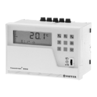
RDT 100: Electronic controller for ventilation and air-conditioning
For universal, autonomous use in ventilation and air-conditioning systems or similar; with
measurement, control and time functions for controlling temperature, humidity, pressure and flow.
DDC compact controller with PI, two- or three-point control and command, sequence and limitation
functions. Thirty-five configurations of control models available. All parameters are pre-set and enable
commissioning to be executed quickly. Plug-in memory available as an option, for documenting and for
copying the setting parameters.
Front plate with LCD panel, keys and sealable, 3-position sliding switch (manual, automatic,
service); snap-shut flap for covering the service keys and for safeguarding the abridged operating
instructions. Housing 144 × 96 mm (DIN 43700) of flame-resistant, pure-white thermoplastic
(RAL 9010); for mounting onto walls, into control panels or onto top-hat rails as per EN 50022.
PI
Y06366
Baseplate with screw terminals for electric cable of up to 2 × 2.5 mm
2
; cable inlet from behind, above
or below.
Y
1
(Y
2
)
X
i1
(X
i3
)
X
i1
(X
i3
)
Y
1
(Y
2
)
X
i2
PI
PI
PI
Y
1
(Rel.)
X
i1
(X
i3
)
PI
Y
1
X
i1
(X
i3
)
PI
X
i2
(Y
2
)
B06743
Y
1
X
i1
Min
Max
X
i2
PI
PI
100 % setpoint
0
0
actual value X
i3
shift
100 %
B06744
∆
Ws
Xs
F1
FP
100 % control signal
P-band Xp
sequence
y
1
y
2
Type
1)
Range
[°C]
Control modes Voltage Weight
[kg]
RDT 100 F001 –30...150 P, PI, 2pt, 3pt 230 V~ 0.67
RDT 100 F002 –30...150 P, PI, 2pt, 3pt 24 V~ 0.54
Models
Structure of controller 1 output
continuous
Sequence
contin.-contin
Sequence
contin.-2pt
1 output
2pt
1 output
PI (3pt)
1 fixed-value controller: 0 1 15 20
30
with command 2 3 16 22 31
2 fixed-value controller: 12 – – 21
–
with common actual value 13 – – 27 –
with y = min/max selection 14 – – – –
1 controller with command – – – 23 –
with common command – – – 24 –
common actual value; once with command – – – 25 –
common acttual value; common command – – – 28 –
1 cascade controller: 4 5 17 –
32
with command 6 7 18 – 33
1 differential controller: 8 9 – 29
34
with command 10 11 – 26 35
Ranges (depends
on transmitter)
Temperature
[°C or K]
Percentage
[%]
Rel. humidity
[%rh]
Abs. humidity
[g/kg]
Enthalpy
[kJ/kg]
no units
Setpoint X
s
–30...150 °C 0...100 0...100 0.0...20 0...100 –4999...4999
P-band 0.1...250 K 0.1...1000 0.1...100 0.1...100 0.1...100 10...4999
4 universal inputs
2)
1 binary input
2)
Threshold –6 V
Temperature Ni1000 (DIN 43760)
Voltage 0(2)...10 V; R
i
= 100 kΩ Outputs
0...1 V, R
i
= 500 kΩ 2 continuous 0(2)...10 V, load > 5 kΩ
Current 0(4)...20 mA, R
i
= 50 Ω 1 continuous 0...10 V, load > 5 kΩ
Potentiometer 2 kΩ (min.1 kΩ) 2 relays 5(2) A, 250 V~
Power supply 230 V~ +10/-15%; 50...60Hz Degree of protection IP 40 (EN 60529)
24 V~ ± 20%; 50...60 Hz Protection class F001 230V II (IEC 60730)
F002 24V III (IEC 60730)
Power consumption 2.5 VA
P-band X
p
0.1....250 K Wiring diagram A06368
Integral action time T
n
0....9990 s Dimension drawing M368900
Switching difference X
Sd
0.1...180 K Fitting instructions MV 505379
Cycle 1 s Operating instructions 7000835 (Part 1)
Permissible ambient temp. 0...45 °C Commissioning 7000836 (Part 2)
Ambient humidity 5...95 %rh Abridged oper. instructions BA 505380
Accessories
0369739 . . .
Operating instructions (Part 1, Part 2 and Abridged operating instructions)
German 001, French 002, English 003, Italian 004
0369746 001 Cover plate for the whole front; of transparent thermoplastic; sealable
0226187 002* Plug-in dummy for memory slot
0226187 003* Plug-in memory for Flexotron
*)
Dimension drawing or wiring diagram are available under the same number
1)
Operating instructions; since several languages are available, please order as an accessory.
2)
Protected against short-circuiting and over-voltage up to 24 V ac. Current input max 70 mA.
Sauter Components
7146100003 S4