51.377/4
AVM 234S
Sauter Components
Split-range unit (accessory 0313529)
This accessory can be fitted either in the actuator itself or externally in an electrical distribution box. The
starting point U
0
and the control span ∆U can be set with the help of a potentiometer. This makes it pos-
sible to operate several regulating units in sequence or in a cascade with the control signal from the
controller. The input signal (partial range) is converted into an output signal of 0...10 V.
Engineering and installation notes
The ingress of condensate or water droplets etc. along the valve spindle and into the actuator should be
prevented.
The valve is slotted straight onto the actuator and fixed with screws (no further action is required). The
actuator is automatically connected to the valve spindle. The actuator spindle is supplied ex works in the
middle position.
The housing has three pre-scored cable inlets which are broken open automatically when the cable inlet
grommet is screwed in.
The combination of stepping motor and electronics unit enables several actuators of the same type to be
run in parallel. The cross-section of the power cable's wires should be selected according to the cable
length and the number of drives. With five drives connected in parallel and a cable length of 50 m, we
recommend a cross-section of 1.5 mm
2
(power consumption of the actuator × 5).
The actuator can be fitted with a maximum of one 230 V module, one additional accessory (auxiliary
contacts or potentiometer) and the split-range unit.
Fitting outdoors. If the devices are fitted outdoors, additional measures must be taken in order to protect
them from the weather.
Additional technical information
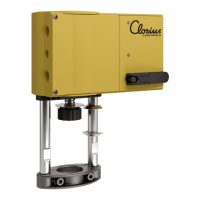
The yellow housing (consisting of the front and back sections and the connecting lid) serves merely as a
cover. The DC motor, the electronics control unit, the load-bearing parts and the maintenance-free gear
unit are accommodated in the housing. The actuator shaft and column are made of rust-proof materials.
The interior plates and the gear unit are made of steel. The valve spindle guide and the valve collar cou-
pling are made of die-cast aluminium.
Note on ambient temperatures: if the temperature of the medium in the valve is up to 110 °C, the ambie nt
temperature may be up to 60 °C. If the temperature of the medium is above 110 °C, the ambient temper-
ature must not exceed 55 °C; alternatively use acce ssory 0372336 180 (adaptor).
Auxiliary change-over contacts
0372333 001 Switching capacity max. 250 V~, min. current 250 mA at 12 V (or 20 mA at 20 V)
Switching capacity max. 12...30 V=, max. current 100 mA
0372333 002 Switching capacity max. 250 V~, min. current 1 mA at 5 V
Switching capacity max. 0.1...30 V=, current 1...100 mA
Even if used only once above 10 mA or up to 50 V, the gold coating will be
destroyed. The switch can then be used only for higher switching outputs.
Warnings
• If the temperature of the medium in the valve is high, the actuator columns and the shaft
may also reach high temperatures.
• Additional protective precautions must be taken if a failure of the final control element
would cause serious damage.
CE conformity
EMC Directive 2004/108/EC Low-Voltage Directive 2006/95/EC
EN 61000-6-2
*)
EN 60730-1
EN 61000-6-4 EN 60730-2-14
Over-voltage category III
Degree of pollution III
*) HF immunity restriction. Feedback signal between 80 MHz and 1000 MHz: criteria B, otherwise criteria A
7151377003 10
 Loading...