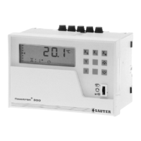
RDT 100 46.100/3
Wiring diagram
0...1V, Pot.
876541917141312151618201110
Yp X1 X2 X3 X4 Y1 Y2 Y3
1 V, 1 mA
Xs ext
Rel. 2Rel. 1
yp
0...1V
xs
ext
xi1 xi2 xi3 xi4 y1 y2 y3 Pot.
87654 19 10 17
M
L
N
0%
P-controller only
Ni1000
0...10 V
0...20 mA
1
2
X
4
X
3
X
2
X
1
RDT 100
xi xi xi
xi
0%
19
Pot. 2000 Ni1000
0(2)...10V
Ri=100k
Ω
0...1V
Ri=500k
Ω
xi
Xs ext.
15 11 17
0(4)...20mA
Ri = 50
Ω
123
M
24 V~
12 Y
A06368d
y
On: Xs=ext.
Off: Xs=int.
VDR
1) 1)
1)
Controller 1
230V~
24V~
F002
F001
1
2
Control models:
No. 0...14 Single controller; continuous
No. 15...18 Single controller; continuous-2-pt
No. 20...29 Single controller; 2-pt
No. 30...39 Single controller; PI (3-pt)
Dimension drawing
Accessories
M00689a
memory
9,411,4
226187
369857
13,4
7,2
15,5
66
72
144
16
92
96
min. 155
7
4
,
5
7,5
74
60 18
92
+0,8/0
138
+1/0 max. 5
Pre-scored slots
Aperture in panel, DIN 43700
Fitted to rail as per EN 50022
M368900
Sauter Components
7146100003 S4
 Loading...