hurrySCAN
®
10, digital, 1064 nm, f = 254 mm
Rev. 2.6 e
4 Installation
23
innovators for industry
4.5 Electrical Connections
Figure 5 on page 18 shows the location of the elec-
trical connectors on the scan head.
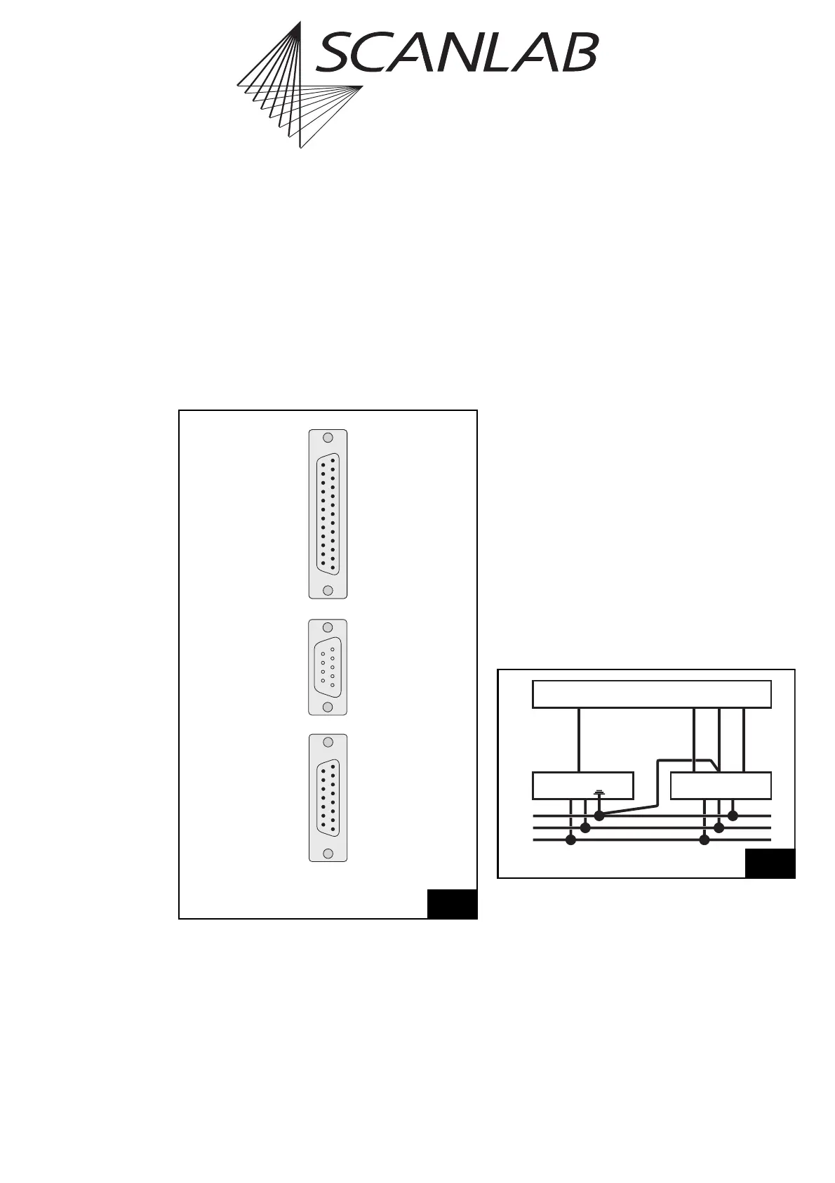
Power Supply
There should be no more than ±5 V potential differ-
ence between the grounds of the power source and
the control computer. Both the power source and the
control computer should be grounded. Usually the
ground of the control computer is already connected
to the mains’s grounding wire (PE) via the mains
cable. Therefore the ground of the power source - i.e.
the GND connector on the output side of your power
supply - should also be connected to the mains's
grounding wire (PE; see “cable 1” in figure 10). The
cable connecting the GND connector with the PC
ground should be as short as possible, as long
connections can also produce excessive potential
differences.
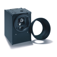
The scan head provides a
25-pin
DIGITAL IN
female
D-SUB connector for data transfer and a
9-pin
POWER IN
male D-SUB
connector
for power supply
as
well as a 15-pin
Z-OUT female
D-SUB-connector for
connecting a Z axis
. Figure 9 shows the pin assign-
ments of the connectors.
9
Pin out of electrical connectors
(13) DO NOT CONNECT
(12) DO NOT CONNECT
(11) DO NOT CONNECT
(10) DO NOT CONNECT
(9) DO NOT CONNECT
(8) DO NOT CONNECT
(7) DO NOT CONNECT
(6) STATUS –
(5) CHAN3 –
(4) CHAN2 –
(3) CHAN1 –
(2) SYNC –
(1) CLOCK –
DO NOT CONNECT (25)
DO NOT CONNECT (24)
DO NOT CONNECT (23)
DO NOT CONNECT (22)
DO NOT CONNECT (21)
DO NOT CONNECT (20)
STATUS+ (19)
CHAN3+ (18)
CHAN2+ (17)
CHAN1+ (16)
SYNC+ (15)
CLOCK+ (14)
DIGITAL IN
(1) – 15 V
(2) – 15 V
(3) GND
(4) +15 V
(5) +15 V
–15 V (6)
GND (7)
GND (8)
+15 V (9)
POWER IN
(8) DO NOT CONNECT
(7) DO NOT CONNECT
(6) DO NOT CONNECT
(5) RESERVED
(4) DO NOT CONNECT
(3) DO NOT CONNECT
(2) DO NOT CONNECT
(1) DO NOT CONNECT
DO NOT CONNECT (15)
DO NOT CONNECT (14)
RESERVED (13)
RESERVED (12)
DO NOT CONNECT (11)
SIG+Z (10)
SIG – Z (9)
Z-OUT
Requirements
For power, the scan head requires a balanced source
of ±(15+1.5) V with a maximum current of 3 A per
pole. The residual ripple of the power source should
not exceed 10 mV
pp
(power sources with larger
residual ripple may be applicable – after reconsulting
SCANLAB – for applications which only require
reduced quality).
Only use a power supply with soft start.
PE
Power supply
PC
Mains
GND
+15V
-15V
Scan head
Data
L
N
Cable 1
10
Connect the power supply’s GND connector and the PC ground to
the mains’s grounding wire (PE).