hurrySCAN
®
10, digital, 1064 nm, f = 254 mm
Rev. 2.6 e
4 Installation
18
innovators for industry
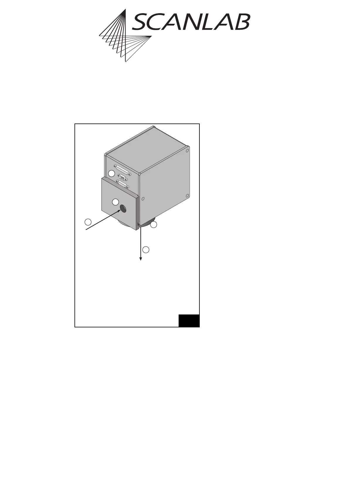
4.3 Layout and Dimensions
Figure 5 shows the layout of the scan head with the
electrical connectors.
Figure 6 on page 19 shows the scan head with its
outer dimensions and the parts which are important
for mounting. The scan head installation is described
in chapter "Mounting the Scan Head", on page 22.
Figure 7 on page 20 and figure 8 on page 21 show
the dimensions necessary for mounting the scan
head and adjusting the scan head with respect to the
working area. Figure 7 depicts the scan head’s
mounting surface with its mounting bore holes and
a bottom view of the scan head (beam exit side)
which shows the displacement of the entry beam axis
from the axis of the objective or from the beam exit
axis (The deflecting mirrors are in their neutral posi-
tions).
Figure 8 shows the following distances:
the working distance A
the distance B between the axis of the input beam
and the lower edge of the housing
the distance C between the axis of the input
beam and the lowest edge of the objective or its
enclosure.
the diameter D which is the larger of the
diameters of the objective and its enclosure.
the distance E between the front edge of the
mounting bracket and the axis of the beam
exiting the scan head.
5
Scan head overview with connector position
5
4
3
1
2
Legend
1Entering beam
2 Beam entrance
3Objective
4Emerging beam
5 Electrical connections