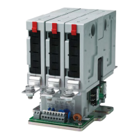
The device described in this manual is the CF series of multipole AC/DC power contactors manufactured by Schaltbau. These contactors are designed for high-voltage switching applications, particularly for inverter-fed alternating current drives with higher frequencies. They are available in configurations for 300 A or 600 A, and can be equipped with normally open (NO) or normally closed (NC) switching chambers, or a combination for change-over (CO) functionality.
Function Description
The CF series contactors are electromechanical switching devices used to control high-power electrical circuits. They operate by using an electromagnetic coil to open or close contacts, thereby making or breaking a circuit. The modular design allows for flexible configurations, supporting 1-pole up to 6-pole setups. A key feature is the newly developed switching elements that can be universally configured as NO, NC, or CO contacts. An efficient electronic economy circuit is integrated to reduce power consumption and heat loss.
For DC contactor types, correct polarity must be observed during connection. For 3,000 V applications, insulating plates are required between switching elements and, depending on the installation, on the outer sides to ensure proper insulation coordination and prevent flashovers.
Important Technical Specifications
- Voltage Range: 1,500 V or 3,000 V AC/DC.
- Current Ratings:
- Continuous current: 200 A, 300 A, and 400 A.
- 600 A can be achieved through parallel connection of two main contacts.
- High rated short-time withstand current up to 4,000 A.
- Frequency: Up to 400 Hertz for inverter-fed AC drives.
- Coil Drive: Available in "wide" (2 drives) and "small" (1 drive) versions, with sophisticated coil saving circuits for low energy consumption and heating.
- Switching Elements:
- NO configuration: Max. 6 switching elements with wide coil drive, max. 3 with small coil drive (for 200 A and 300 A versions). Max. 4 switching elements with wide coil drive, max. 2 with small coil drive (for 400 A versions).
- NC configuration: Max. 4 switching elements with wide coil drive, max. 2 with small coil drive (for 200 A and 300 A versions). Max. 4 switching elements with wide coil drive, max. 2 with small coil drive (for 400 A versions).
- CO configuration: Up to 3 CO contactors with wide coil drive, 1 CO contactor with small coil drive (for 200 A and 300 A versions). Up to 2 CO contactors with wide coil drive, 1 CO contactor with small coil drive (for 400 A versions).
- Auxiliary Switches: Up to 4 auxiliary switches can be integrated for diagnosis and switching status monitoring.
- Mounting: Designed for horizontal or vertical mounting. Suspended overhead mounting is not permitted.
- Clearances: Minimum clearances to earth potential and insulating structure parts, as well as between control voltage wires and main connections, must be maintained to prevent flashovers. These are specified in the C60 catalogue.
- Overvoltage Limitation: The value of overvoltage limitation is part of the magnetic system and must not be modified or short-circuited.
Usage Features
- Modular Design: High modularity allows for a wide range of configuration options, making them adaptable for various industrial applications and suitable for both new projects and modernizations.
- Application Versatility: Can be used with electrical systems for special applications, including inverter-fed alternating current drives.
- Safety: Equipped with protective earth terminals. Unprotected live parts carry warning labels that must be observed. Proper installation of arc chambers and switching element covers is mandatory.
- Ambient Conditions: Designed for specific ambient conditions (temperature ranges, degree of soiling) as defined in the C60 catalogue. Protection from moisture and dust is required during installation, operation, and storage.
- Handling: Devices must be handled with care to avoid damage (breaks, cracks, deformation). Some types contain permanent magnets that can attract ferromagnetic parts or damage magnetic strips on cards, requiring careful placement and storage.
Maintenance Features
The CF series contactors are largely maintenance-free within their rated mechanical life. Electrical life depends on load conditions and switching cycles.
- Easy Maintenance:
- Toolless inspection of main contact tips.
- Toolless replacement of arc chamber inserts.
- Regular Tests/Checks:
- External visual inspection: Annually (more frequently in dirty environments) to check for dirt, damage, wear, and proper seating of covers.
- Main contacts check: 1-2 times per year to inspect for damage, wear, and combustion residue. Replacement is necessary if more than 70% of contact material is burnt through.
- Auxiliary switches check: Every 2 years to inspect for dirt, damage, wear, and signs of short circuits.
- Cables/busbars and earthing cable check: Regularly for damage, insulation, corrosion, kinks, loose or missing fastening elements, and correct tightening torque.
- Base plate/mounting flange check: Regularly for loose or missing fastening elements.
- Corrective Maintenance:
- Replacing arcing chamber inserts: If damaged or heavily worn, all inserts must be replaced. This involves sliding the latching button upwards, removing the old insert, pushing in the new one, and releasing the button.
- Replacing switching elements: If the housing is damaged, heavily worn, or more than 70% of contact material is burnt through, the entire switching element must be replaced. This involves unscrewing fixing screws, removing the old element, installing the new one, and tightening screws to 5 Nm.
- Replacing auxiliary switches: If damaged (e.g., due to a short circuit in the control circuit), all auxiliary switches must be replaced. This involves pulling off receptacles, unscrewing plastic self-tapping screws, removing the old switch, positioning the new one, lightly screwing it in, checking alignment, tightening to 0.8 Nm, and plugging receptacles back on.
- Post-Maintenance Checks: After any installation or maintenance, a complete check of the contactor's correct operation must be performed according to EN/IEC 60077-2 and EN/IEC 60947-4-1 standards. This includes verifying installation, main circuit connections, polarity (for DC), earthing, insulating plates, coil control wires, auxiliary switch connections, pull-in/drop-off voltage, wiring routing, and label stickers.
- Spare Parts: A list of spare parts is provided, including arcing chamber inserts (plastic, metal arcing plates, ceramic for 200/300 A and 400 A), complete switching elements (NO/NC for 200/300 A and 400 A), auxiliary switches (gold/silver contacts), insulating plates, and complete coil drive units (wide/small). When ordering, the precise type and article number from the rating plate are required.