11
2019-03-06 / V1.0
Contactors CT/CU Series – Installation and Maintenance Instructions
Description
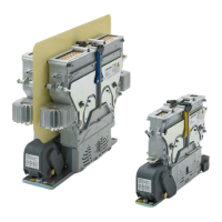
Single pole NO contactors for DC/AC
CT/CU 1115 CT/CU 1130
B
C
D
H
F
CT/CU 1115/11 single pole NO contactor for 1,500 V / 1100 A
B
C
D
H
F
CT/CU 1130/11 single pole NO contactor for 3,000 V / 1100 A
A Release slider to unlock arc chute
B Lock bar with indicator (arc chute open/locked)
- yellow: mounting pos. H (horizontal)
- red: mounting pos. V (vertical)
- blue: mounting pos. either H (horizontal) or V (vertical)
C Arc chute
D Latching lever
E Main terminal
F Auxiliary contact block (incl. cover)
G Coil terminal WAGO 264 (incl. cover)
H Main terminal with heat sink
Double pole NO contactors for DC/AC
CT/CU 1215 CT/CU 1230
13
B
C
D
E
F
CT/CU 1215/04 double pole NO contactor for 1,500 V / 400 A
13
B
C
D
E
F
CT/CU 1230/04 double pole NO contactor for 3,000 V / 400 A
A Release slider to unlock arc chute
B Lock bar with indicator (arc chute open/locked)
- yellow: mounting pos. H (horizontal)
- red: mounting pos. V (vertical)
- blue: mounting pos. either H (horizontal) or V (vertical)
C Arc chute
D Latching lever
E Main terminal
F Auxiliary contact block (incl. cover)
G Coil terminal WAGO 264 (incl. cover)
H Main terminal with heat sink
 Loading...