Installation instructions for adapter AD 01...03
10
Date: 01.08.2012 822.371 BA / EN
8 Electrical connection
Y WARNING!
Reverse poling!
Damage to the electrical system of the basis vehicle:
F Ensure that the required voltage levels of the control voltages match
the values required.
F Only carry out electrical connection work when the system is isolated
from the power supply.
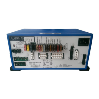
Connect the adapter in the following sequence (also refer to the block dia-
gram and the view in the instruction manual):
1. All connectors to consumers (additional lights, heater, any other devices)
2. Control voltages from basis vehicle (B4)
3. Battery voltage from basis vehicle (B1)
Disconnect in the reverse order.
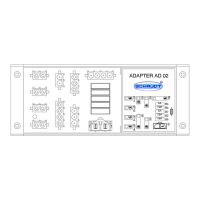
8.1 Block diagram/wiring diagram
Y The block diagram/wiring diagram are in the appendix of the instruction
manual for the AD 01 and AD 02 adapters.
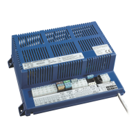
8.2 Connecting peripheral devices
Y ATTENTION!
Short circuits!
Damage to the adapter or cable fire:
F To protect the supply lines in the event of a short circuit, connect the
fuses directly to the positive terminal of battery.
The supply lines (to B1) must be fused by the basis vehicle in line with
their cross section.
Select cable cross-sections in line with EN 1648-1/-2. The maximum current
load must not exceed 90% of the individual fuse rating.
Connection sequence
Disconnection
Fuse protection