Installation instructions for adapter AD 01...03
9
Date: 01.08.2012
822.371 BA / EN
7 Mechanical installation
The device is intended as a wall-mounted device (with fuses facing forwards)
or as a floor-mounted device.
Select a dry place for installation.
Ensure a minimum clearance to the surrounding fixtures and fittings:
F Maintain a gap of at least 1 cm on all sides (except mounted side).
F Whilst in operation, the ambient temperature must not exceed +70 C,
measured 2.5 cm away from the sides of the device.
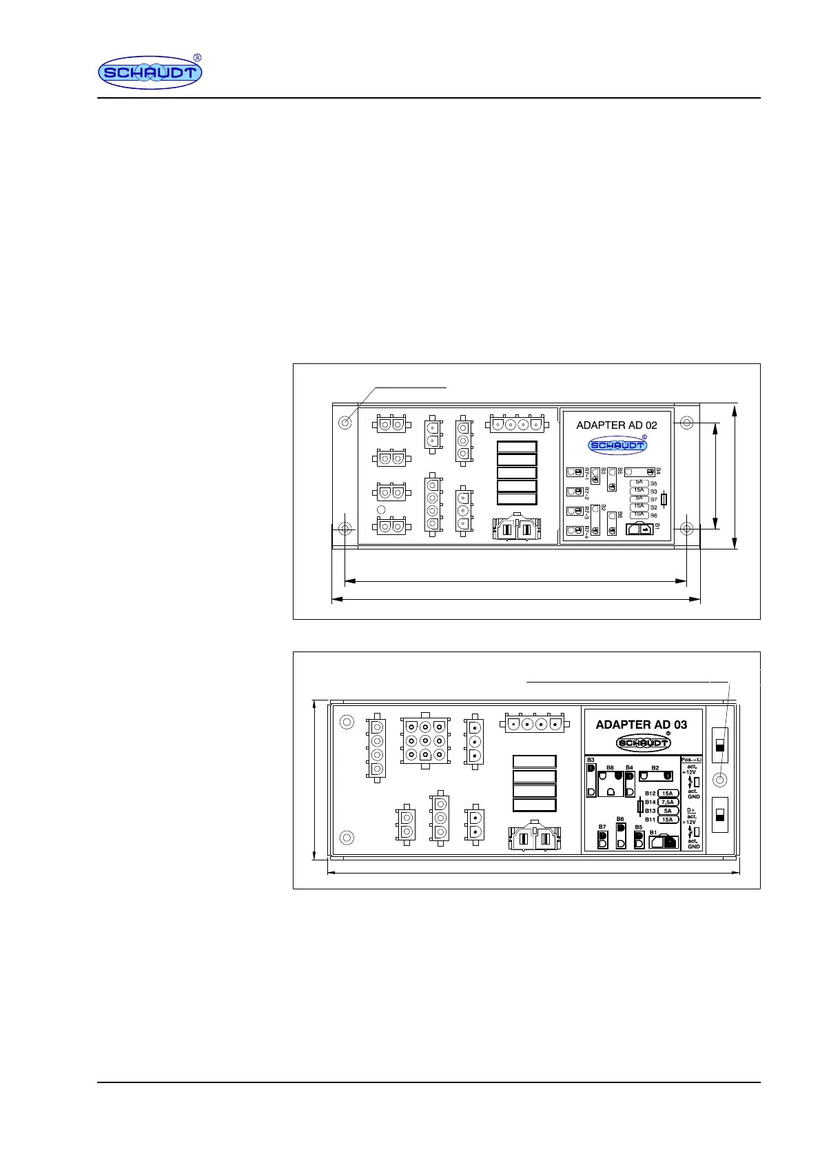
Screw the adapter onto a firm, flat base with four (or three for the AD 03)
screws (3.5mm diameter) at the four fitting holes provided.
Top
view
4x 3.5
Front of device
172
184
53
73
Fig. 5 Dimension diagram of AD 01 and AD 02 adapters (dimensions in mm)
73
189
Installation distance rolls for
attachment with 3.5 screws
3x3.7
Fig. 6 Dimension diagram for AD 03 adapter (dimensions in mm)
Environment
Minimum clearance
Fitting