Instruction Manual for Electroblock EBL 271
14
Date: 14.02.2011 811.523 BA / EN
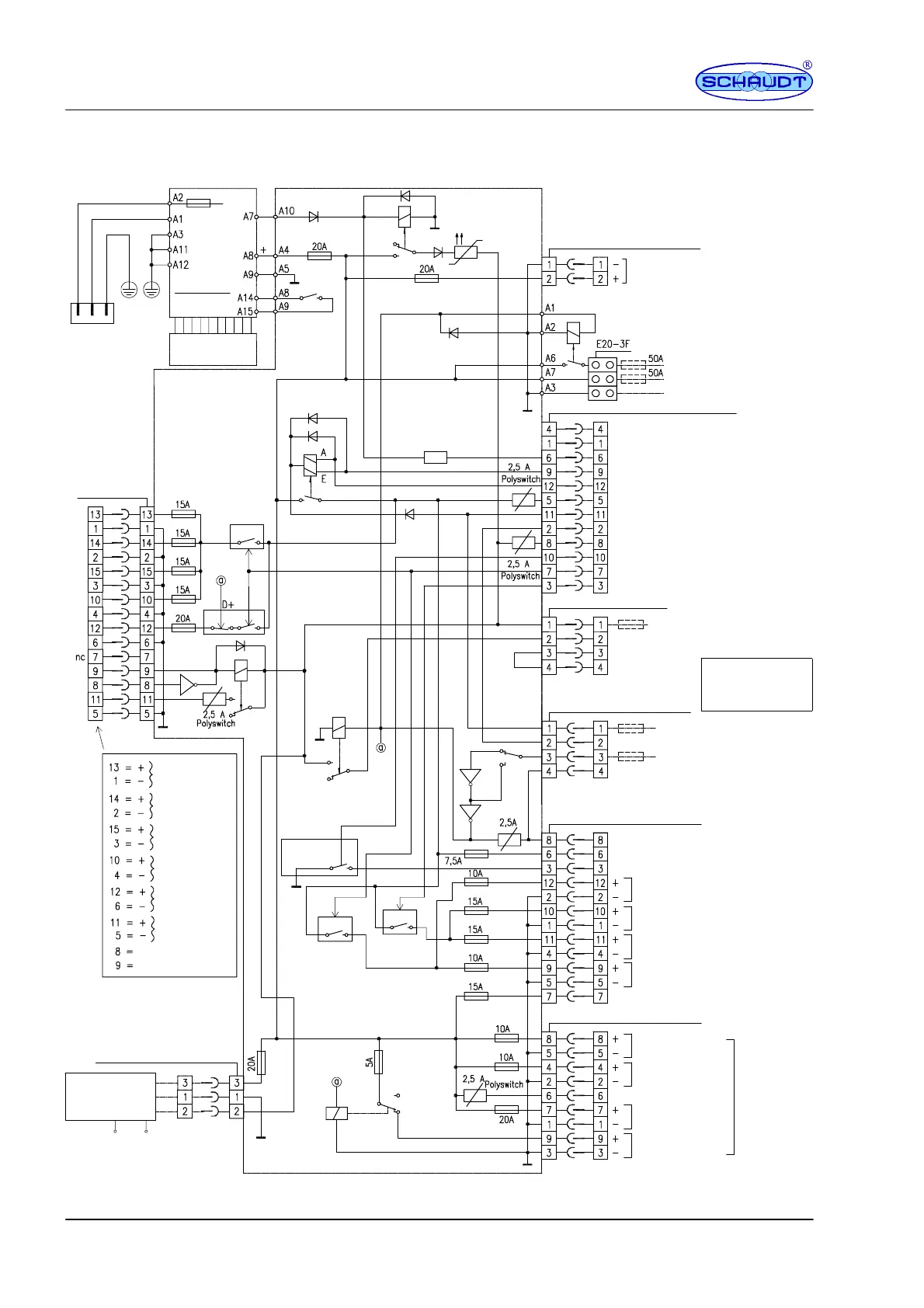
F Block diagram/wiring diagram
Charging relay
Battery 1
MNL socket, 2F block 3
Auxiliary charger
Battery
cut--out relay, 70A
LAS 1218
14.3V--18A
S 1218
Mains 230V~50Hz
IEC connector
Changeover switch
lead acid
lead gel/
Plug connector MSFQ/O 12F -- block 8
+ living area battery (batt.2)
Negative living area battery
+ Starter battery (batt.1)
nc
nc
Pump switch
Spare
Mains indicator
Light
+ sensor, living area battery (batt. 2)
12V indicator
+ Starter battery (batt.1)
12V ON
12V OFF
Minus sensor living area battery (batt. 2)
Minifit SR 4F -- block 1
+ batt. 1 for refrigerator *
Minus batt.1 for
Negative, refrigerator
Refrigerator lines
must be routed separately
from other battery
lines to the
battery terminals.
*
+ Refrigerator
refrigerator *
20A
Negative living area battery sensor
+ sensor, living area battery
D+ input
MNL socket 4F -- block 5
D+ point
2A
2A
D+ point
+Pump
Connected negative pole of pump
Light 1
Light 2
Spare 1
MNL socket 12F -- block 6
Spare 1
+ Continual positive for radio
MNL socket 9F -- block 4
TV
Awning light
Step
Heater
Permanent
12V
Refrigerator controller
KPL EBL 271 PCB
MNL socket
3F block 2
SB +
LR ...
Solar
charge regulator
Solar module
WB--
--
Switching stage
Spare 3
Spare 4
Spare 5
Spare 6
Foldaway bed
Marker
lights BL
+ Control signal BG
-- Control signal BG
Fridge --
Relay
HS relay
(60A)
MNL--
Socket
15F -- Block 7